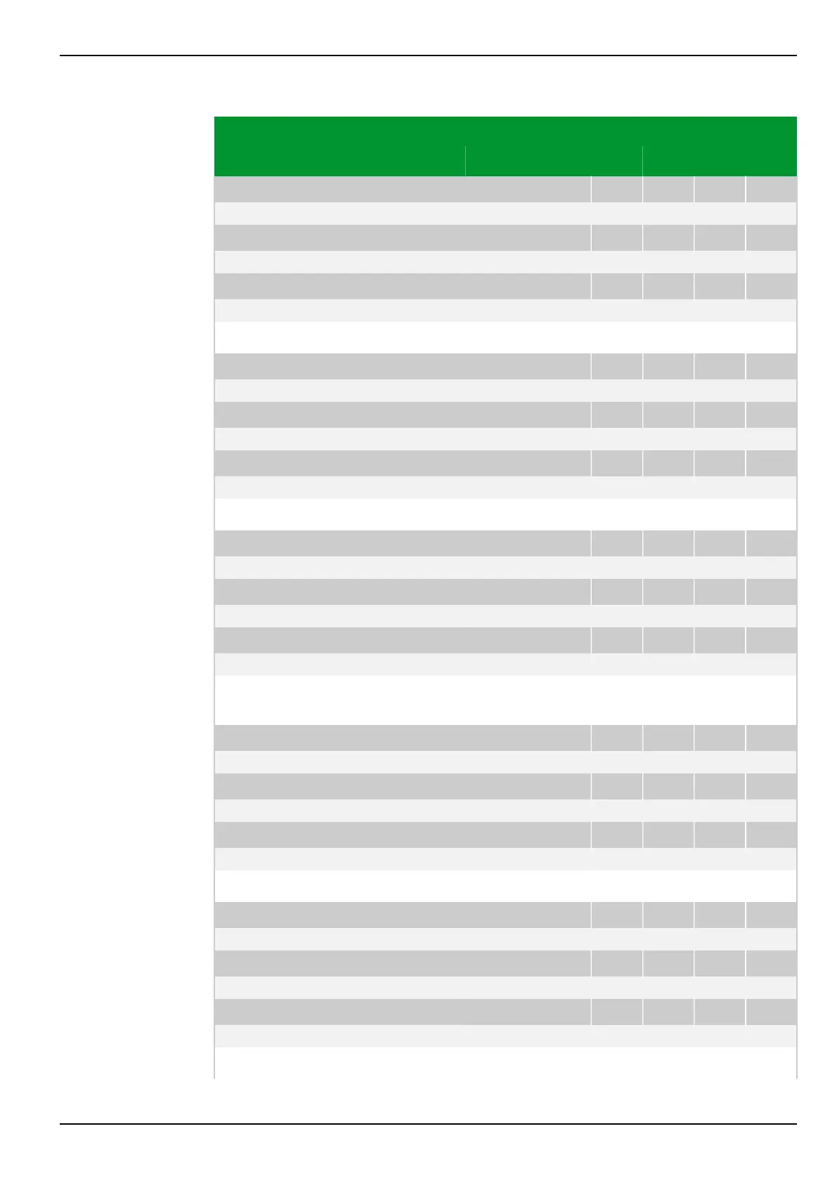
Parameter Address
Default Min Max Unit Logic Diagram
[spacer]
IDMT1: Factor kt,P PSx
081 054 082 054 083 054 084 054
1.00 0.05 10.00 Fig. 3-121, (p. 3-167)
[spacer]
IDMT2: Factor kt,P PSx
081 174 082 174 083 174 084 174
1.00 0.05 10.00
[spacer]
IDMT3: Factor kt,P PSx
081 194 082 194 083 194 084 194
1.00 0.05 10.00
[spacer]
Setting for the factor kt,P of the starting characteristic (phase current system).
[spacer]
IDMT1: Min. trip t. P PSx
081 057 082 057 083 057 084 057
1.00 0.00 10.00 s Fig. 3-121, (p. 3-167)
[spacer]
IDMT2: Min. trip t. P PSx
081 177 082 177 083 177 084 177
1.00 0.00 10.00 s
[spacer]
IDMT3: Min. trip t. P PSx
081 197 082 197 083 197 084 197
1.00 0.00 10.00 s
[spacer]
Setting for the minimum trip time (phase current system).
[spacer]
IDMT1: Hold time P PSx
081 055 082 055 083 055 084 055
0.00 0.00 600.00 s Fig. 3-121, (p. 3-167)
[spacer]
IDMT2: Hold time P PSx
081 175 082 175 083 175 084 175
0.00 0.00 600.00 s
[spacer]
IDMT3: Hold time P PSx
081 195 082 195 083 195 084 195
0.00 0.00 600.00 s
[spacer]
Setting for the hold time for storing the starting time once the starting has
dropped out (phase current system).
[spacer]
IDMT1: Release P PSx
081 056 082 056 083 056 084 056
1: Without delay Fig. 3-121, (p. 3-167)
[spacer]
IDMT2: Release P PSx
081 176 082 176 083 176 084 176
1: Without delay
[spacer]
IDMT3: Release P PSx
081 196 082 196 083 196 084 196
1: Without delay
[spacer]
Setting for the reset characteristic (phase current system).
[spacer]
IDMT1: Iref,neg PSx
081 111 082 111 083 111 084 111
Blocked 0.01 0.80 Inom Fig. 3-122, (p. 3-169)
[spacer]
IDMT2: Iref,neg PSx
081 121 082 121 083 121 084 121
Blocked 0.01 0.80 Inom
[spacer]
IDMT3: Iref,neg PSx
081 131 082 131 083 131 084 131
Blocked 0.01 0.80 Inom
[spacer]
Setting for the reference current (negative-sequence current system).
7 Settings P634
P634/EN M/R-42-A // P634‑311‑653 7-169
 Loading...
