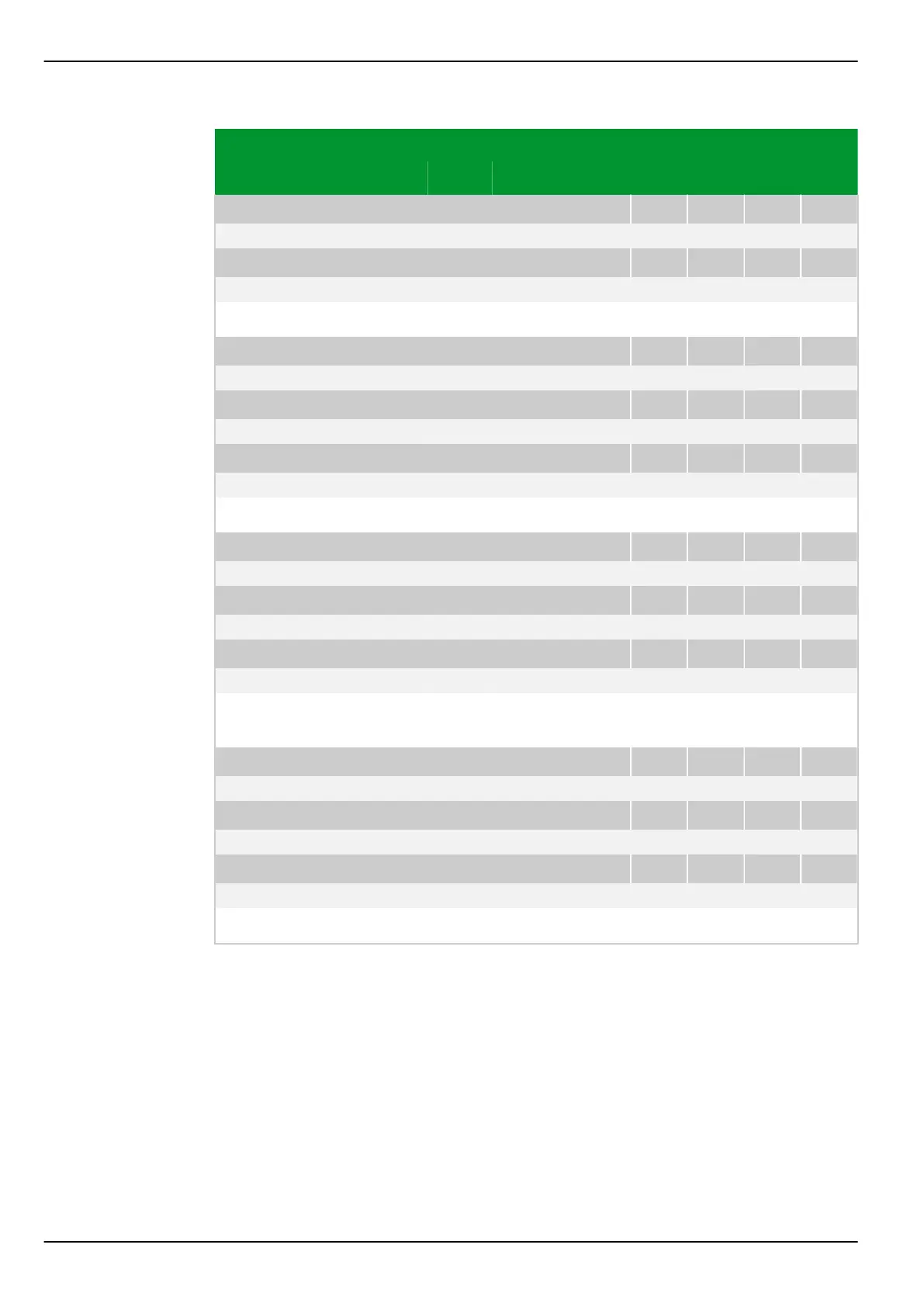
Parameter Address
Default Min Max Unit Logic Diagram
[spacer]
IDMT2: Factor kt,N PSx
081 184 082 184 083 184 084 184
1.00 0.05 10.00
[spacer]
IDMT3: Factor kt,N PSx
081 204 082 204 083 204 084 204
1.00 0.05 10.00
[spacer]
Setting for the kt,N factor of the starting characteristic (residual current system).
[spacer]
IDMT1: Min. trip t. N PSx
081 067 082 067 083 067 084 067
1.00 0.00 10.00 s Fig. 3-123, (p. 3-170)
[spacer]
IDMT2: Min. trip t. N PSx
081 187 082 187 083 187 084 187
1.00 0.00 10.00 s
[spacer]
IDMT3: Min. trip t. N PSx
081 207 082 207 083 207 084 207
1.00 0.00 10.00 s
[spacer]
Setting for the minimum trip time characteristic (residual current system).
[spacer]
IDMT1: Hold time N PSx
081 065 082 065 083 065 084 065
0.00 0.00 600.00 s Fig. 3-123, (p. 3-170)
[spacer]
IDMT2: Hold time N PSx
081 185 082 185 083 185 084 185
0.00 0.00 600.00 s
[spacer]
IDMT3: Hold time N PSx
081 205 082 205 083 205 084 205
0.00 0.00 600.00 s
[spacer]
Setting for the hold time for storing the starting time once the starting has
dropped out (residual current system).
[spacer]
IDMT1: Release N PSx
081 066 082 066 083 066 084 066
1: Without delay Fig. 3-123, (p. 3-170)
[spacer]
IDMT2: Release N PSx
081 186 082 186 083 186 084 186
1: Without delay
[spacer]
IDMT3: Release N PSx
081 206 082 206 083 206 084 206
1: Without delay
[spacer]
Setting for the reset characteristic (residual current system).
P634 7 Settings
7-172 P634/EN M/R-42-A // P634‑311‑653
 Loading...
