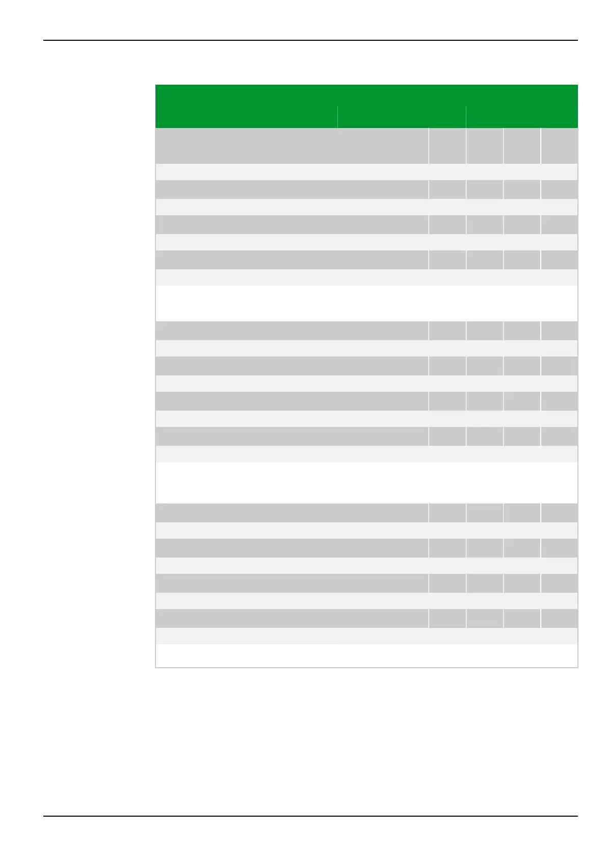
Parameter Address
Default Min Max Unit Logic Diagram
Measuring-circuit
monitoring
MCM_1: Enable PSx
081 038 082 038 083 038 084 038
0: No
[spacer]
MCM_2: Enable PSx
081 039 082 039 083 039 084 039
0: No
[spacer]
MCM_3: Enable PSx
081 040 082 040 083 040 084 040
0: No
[spacer]
MCM_4: Enable PSx
081 041 082 041 083 041 084 041
0: No
[spacer]
This setting defines the parameter subset in which measuring-circuit monitoring
is enabled.
[spacer]
MCM_1: Ineg/Ipos> PSx
081 042 082 042 083 042 084 042
0.30 0.20 1.00 Fig. 3-157, (p. 3-203)
[spacer]
MCM_2: Ineg/Ipos> PSx
081 043 082 043 083 043 084 043
0.30 0.20 1.00
[spacer]
MCM_3: Ineg/Ipos> PSx
081 044 082 044 083 044 084 044
0.30 0.20 1.00
[spacer]
MCM_4: Ineg/Ipos> PSx
081 045 082 045 083 045 084 045
0.30 0.20 1.00
[spacer]
Setting for the operate value for the ratio I
neg
/I
pos
.
(I
neg
= negative-sequence current, I
pos
= positive-sequence current)
[spacer]
MCM_1: Operate delay PSx
081 046 082 046 083 046 084 046
5.00 0.10 100.00 s Fig. 3-157, (p. 3-203)
[spacer]
MCM_2: Operate delay PSx
081 047 082 047 083 047 084 047
5.00 0.10 100.00 s
[spacer]
MCM_3: Operate delay PSx
081 048 082 048 083 048 084 048
5.00 0.10 100.00 s
[spacer]
MCM_4: Operate delay PSx
081 049 082 049 083 049 084 049
5.00 0.10 100.00 s
[spacer]
Setting for the operate delay.
7.1.3.4 Control
7 Settings
P634
P634/EN M/R-42-A // P634‑311‑653 7-183