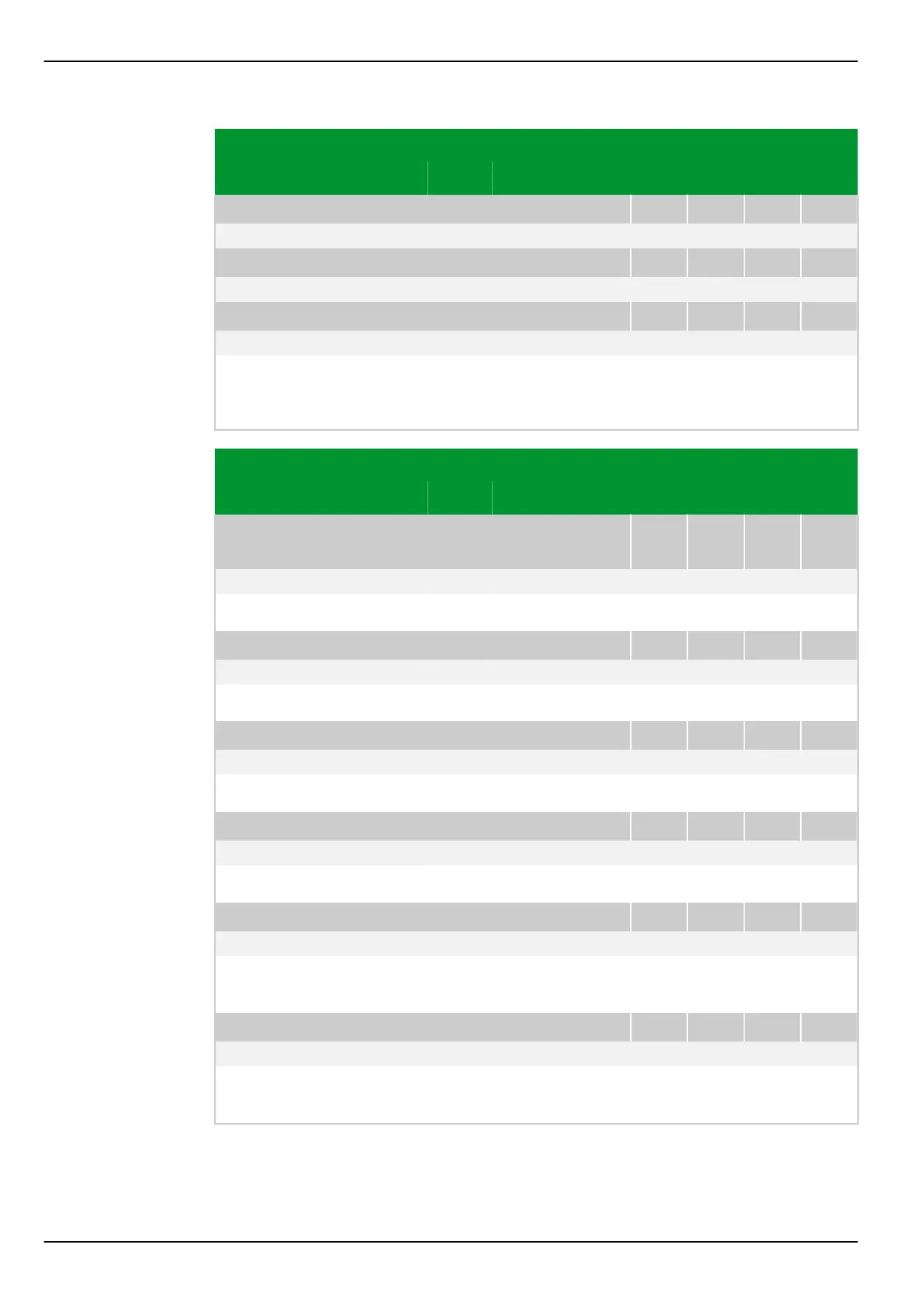
Parameter Address
Default Min Max Unit Logic Diagram
[spacer]
MAIN: Angle phi NY, end a
005 077
Not measured -180.0 180.0 ° Fig. 3-54, (p. 3-85)
[spacer]
MAIN: Angle phi NY, end b
005 078
Not measured -180.0 180.0 ° Fig. 3-54, (p. 3-85)
[spacer]
MAIN: Angle phi NY, end c
005 079
Not measured -180.0 180.0 ° Fig. 3-54, (p. 3-85)
[spacer]
Display of the phase displacement between the residual current calculated by
the P634 from the three phase currents and the current measured at the T14,
T24 or T34 transformer.
Parameter Address
Default Min Max Unit Logic Diagram
Differential protec‐
tion
DIFF: Diff. current 1
005 080
Not measured 0.000 40.000 Iref Fig. 3-98, (p. 3-140)
[spacer]
Display of differential current, measuring system 1, referred to I
ref
.
[spacer]
DIFF: Restrain. current 1
005 081
Not measured 0.000 40.000 Iref Fig. 3-98, (p. 3-140)
[spacer]
Display of restraining current, measuring system 1, referred to I
ref
.
[spacer]
DIFF: Diff. current 2
006 080
Not measured 0.000 40.000 Iref Fig. 3-98, (p. 3-140)
[spacer]
Display of differential current, measuring system 2, referred to I
ref
.
[spacer]
DIFF: Restrain. current 2
006 081
Not measured 0.000 40.000 Iref Fig. 3-98, (p. 3-140)
[spacer]
Display of restraining current, measuring system 2, referred to I
ref
.
[spacer]
DIFF: Diff. current 3
007 080
Not measured 0.000 40.000 Iref Fig. 3-98, (p. 3-140)
[spacer]
Display of the differential current for measuring system 1, 2 or 3, respectively,
referred to I
ref
.
[spacer]
DIFF: Restrain. current 3
007 081
Not measured 0.000 40.000 Iref Fig. 3-98, (p. 3-140)
[spacer]
Display of the restraining current for measuring system 1, 2 or 3, respectively,
referred to I
ref
.
P634 8 Information and Control Functions
8-14 P634/EN M/R-42-A // P634‑311‑653