Parameter Address
Default Min Max Unit Logic Diagram
[spacer]
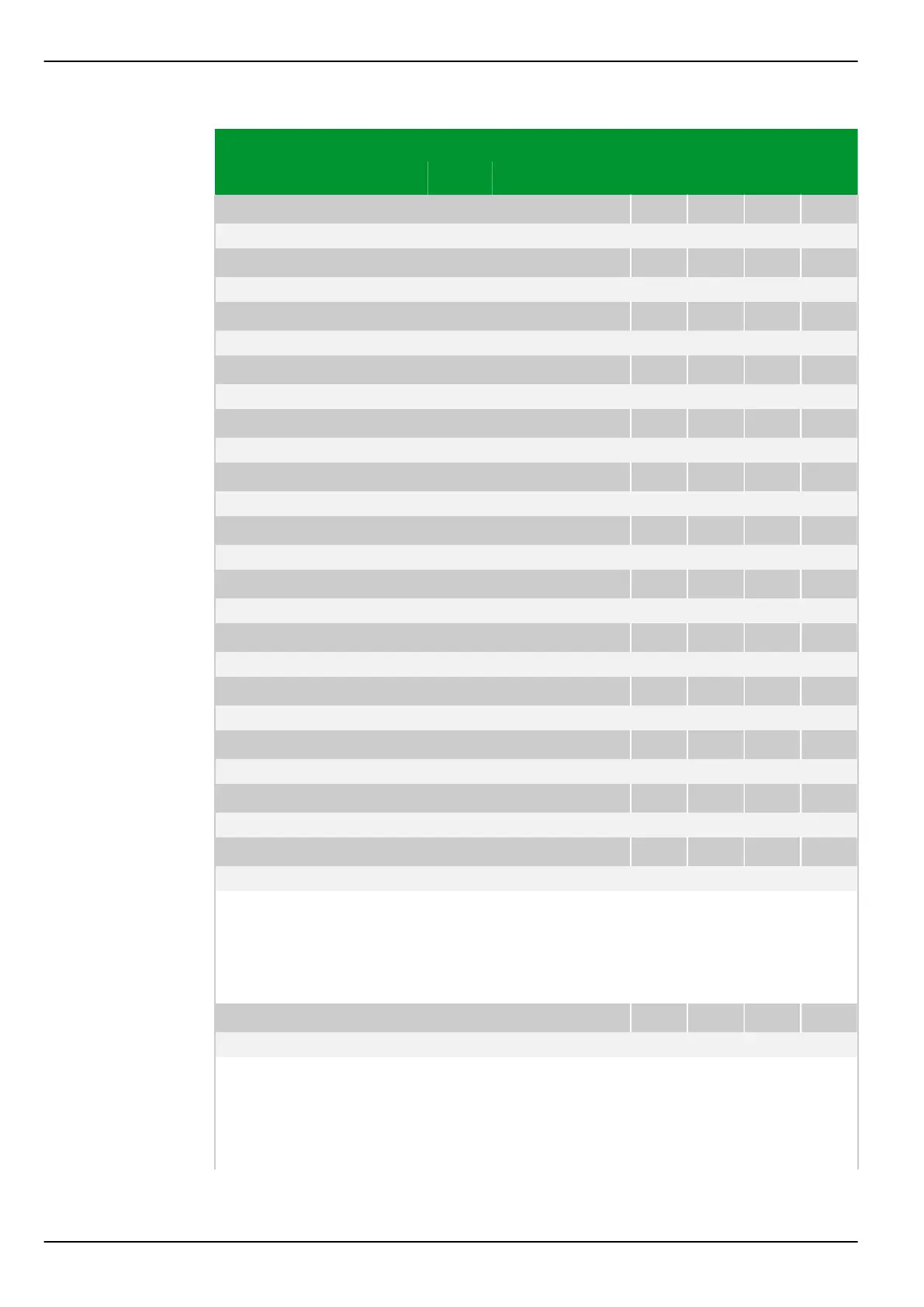
GOOSE: ExtDev20 link faulty
107 235
0: No
[spacer]
GOOSE: ExtDev21 link faulty
107 236
0: No
[spacer]
GOOSE: ExtDev22 link faulty
107 237
0: No
[spacer]
GOOSE: ExtDev23 link faulty
107 238
0: No
[spacer]
GOOSE: ExtDev24 link faulty
107 239
0: No
[spacer]
GOOSE: ExtDev25 link faulty
107 240
0: No
[spacer]
GOOSE: ExtDev26 link faulty
107 241
0: No
[spacer]
GOOSE: ExtDev27 link faulty
107 242
0: No
[spacer]
GOOSE: ExtDev28 link faulty
107 243
0: No
[spacer]
GOOSE: ExtDev29 link faulty
107 244
0: No
[spacer]
GOOSE: ExtDev30 link faulty
107 245
0: No
[spacer]
GOOSE: ExtDev31 link faulty
107 246
0: No
[spacer]
GOOSE: ExtDev32 link faulty
107 247
0: No
[spacer]
Display when GOOSE receipt of the configured external device is faulty or not
available. To each GOOSE the GOOSE sending device will attach a validity
stamp, up to which a repetition of GOOSE will be carried out independent of a
change of state. Thus the unit monitors the time period at which the next state
signal must be received.
[spacer]
GOOSE: IED link faulty
107 250
0: No
[spacer]
Display which appears as soon as receipt of at least one of the configured
GOOSEs is faulty or not available. To each GOOSE the GOOSE sending device
will attach a validity stamp, up to which a repetition of GOOSE will be carried out
independent of a change of state. Thus the unit monitors the time period at
which the next state signal must be received.
P634 8 Information and Control Functions
8-68 P634/EN M/R-42-A // P634‑311‑653
 Loading...
