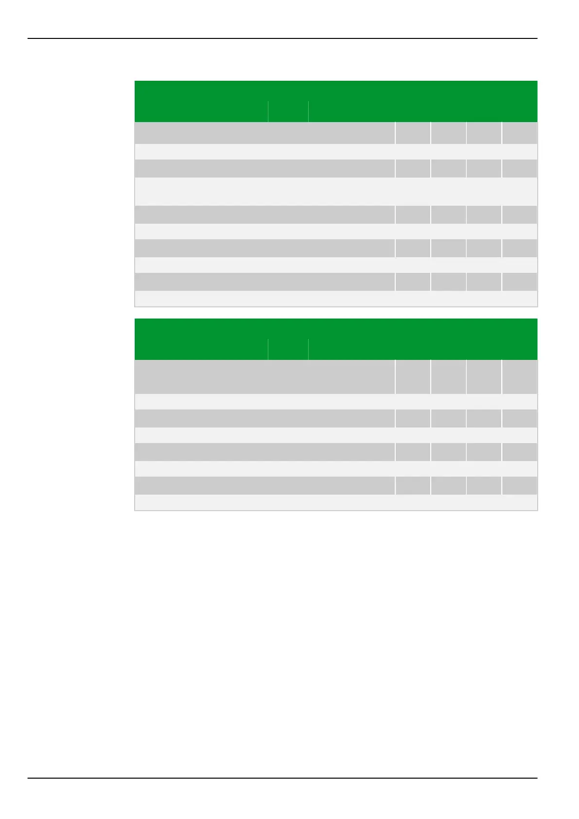
Parameter Address
Default Min Max Unit Logic Diagram
Measured data input
MEASI: Reset Tmax EXT
006 076
0: No
[spacer]
MEASI: Enabled
035 008
0: No Fig. 3-23, (p. 3-39)
Fig. 3-31, (p. 3-48)
[spacer]
MEASI: PT100 faulty
040 190
0: No Fig. 3-28, (p. 3-44)
[spacer]
MEASI: Overload 20mA input
040 191
0: No Fig. 3-26, (p. 3-42)
[spacer]
MEASI: Open circ. 20mA inp.
040 192
0: No Fig. 3-26, (p. 3-42)
Parameter Address
Default Min Max Unit Logic Diagram
Binary and analog
output
OUTP: Block outp.rel. EXT
040 014
0: No
[spacer]
OUTP: Reset latch. EXT
040 015
0: No
[spacer]
OUTP: Outp. relays blocked
021 015
1: Yes Fig. 3-29, (p. 3-46)
[spacer]
OUTP: Latching reset
040 088
0: No Fig. 3-29, (p. 3-46)
P634 8 Information and Control Functions
8-70 P634/EN M/R-42-A // P634‑311‑653
 Loading...
