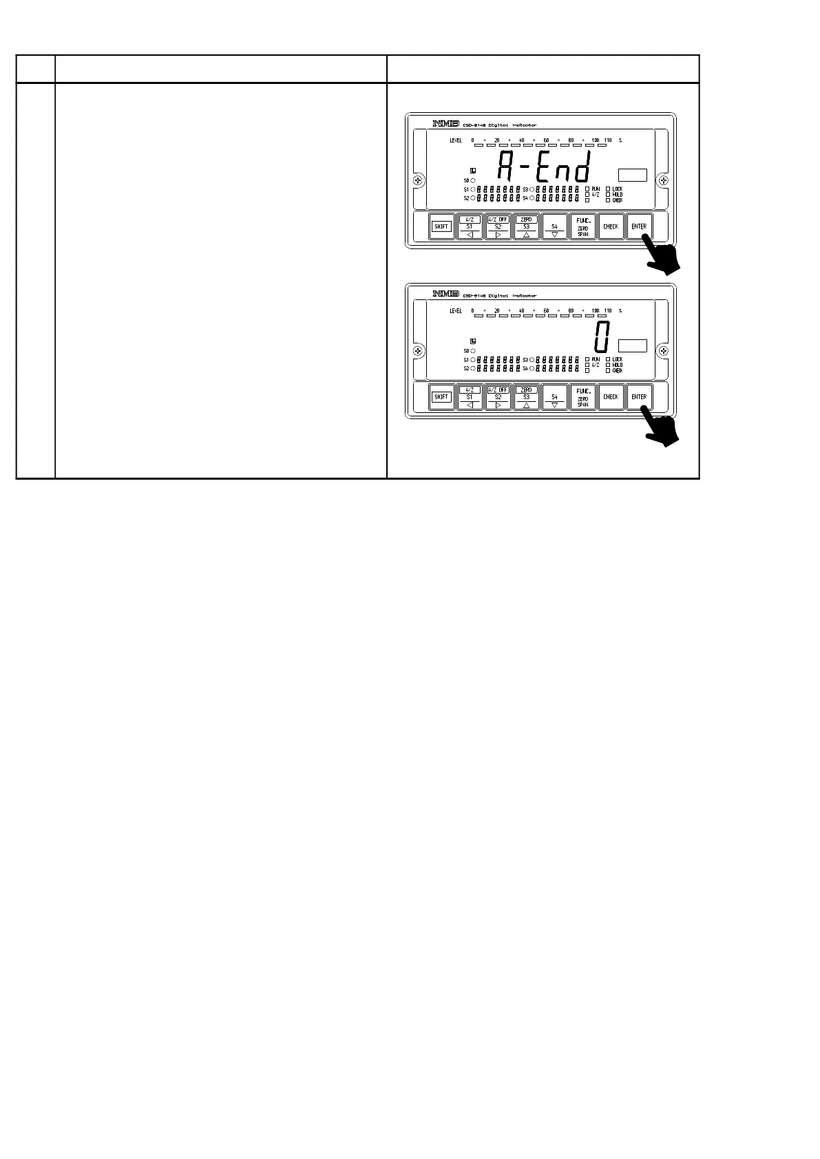
Home
Minebea
Measuring Instruments
CSD-814B
Minebea CSD-814B User Manual
4
of 1
of 1 rating
183 pages
Give review
Manual
Specs
To Next Page
To Next Page
To Previous Page
To Previous Page
Loading...
94
Procedures
5
Press
the
key
.
The
load
display
shows
“
A−END”.
By
pressing
the
key
again,
quits
the
VCAL
mode
and
returns
to
Measurement
mode,
then
the
load
value
displays.
At
the
same
time,
result
of
fine
adjustment
on
the
minimum/the
maximum
analog
output
value
will
be
renewed.
106
108
Table of Contents
1−1. Installation
5
Power Supply
6
Application Notes
6
Record of Revision
8
Table of Contents
9
General
14
1−1. Features
14
Each Name and Function
15
2−1. Front Panel
15
2−2. Rear Panel
17
Installation Procedures
18
3−1. Installation Place
18
3−2. Location Where Installation Is Not Allowed
18
3−3. Installation
19
Connecting Method
20
4−1. Layout of Terminal
20
4−2. Note on Connection
21
4−3. Connection
22
4−3−1. Connection with Strain Gage Applied Transducers
22
4−3−2. Connection with External Control Input
29
4−3−3. Connection with Contact Output
30
4−3−4. Connection with Power Supply and Ground
31
4−3−5. Connection with Options
31
Calibration Procedure
32
5−1. Preparations
32
5−2. Calibration Procedures
32
5−2−2. Fine Adjustment Mode
38
5−3. Selection of Calibration Procedures on each Condition
41
5−3−1. to Make Calibration on the Instrument
42
5−3−2. in Case of Executing Recalibration
45
Operating Procedures
46
6−1. Key
46
Simultaneously in Measurement Mode
46
For Comparator S1, S2, S3, and S4
46
6−2. Key
46
6−2−1. Single Key Is Pressed in Measurement Mode
46
6−2−2. When Pressed with the Key Together in Measurement Mode
46
6−2−3. When Operated in Fine Adjustment Mode for Zero and Span
46
6−2−4. When Operation Is Made in Another Mode
47
6−3. Key
47
6−3−1. Single Key Is Pressed in Measurement Mode
47
6−3−2. When Pressed with the Key Together in Measurement Mode
47
6−3−3. When Operated in Fine Adjustment Mode for ZERO and SPAN
47
6−3−4. Operation Is Made in Another Mode
48
6−4. Key
48
6−4−1. Single Key Is Pressed in Measurement Mode
48
6−4−2. When Pressed with the Key Together in Measurement Mode
48
6−4−3. When Operated in Fine Adjustment Mode for ZERO and SPAN
48
6−4−4. When Operation Is Made in the Other Mode
48
6−5. Key
49
6−5−1. Press Key in the Measurement Mode
49
6−5−2. When Operated in Fine Adjustment Mode for ZERO and SPAN
49
6−5−3. When Operation Is Made in the Other Mode
49
6−6. Key
49
6−6−1. When Pressed in Measurement Mode
49
6−6−2. When Operated in the Fine Adjustment Mode for ZERO and SPAN
49
6−6−3. When Operation Is Made in the Other Mode
49
6−7. Key
50
6−7−1. When Pressed Singly in Measurement Mode
50
6−7−2. When Pressed with the Key Together in Measurement Mode
50
6−7−3. Pressed in the Fine Adjustment for ZERO and SPAN
50
6−7−4. When Operation Is Made in Another Mode
50
6−8. Key
50
Function and Operation
51
7−1. External Control Input Signal, Contact Output Signal
51
7−1−1. External Control Input Signal
51
7−1−2. Contact Output Signal
52
7−1−3. Equivalent Circuit
52
7−2. Comparator
53
7−2−1. Change of Set Value
53
7−2−2. Operation on Comparator S1, S2, S3 and S4
56
7−2−3. Comparative Target for Comparator S1, S2, S3 and S4
57
7−2−4. Operation of Comparator so
58
7−2−5. Hysteresis on Comparator
61
7−3. How to Use Filter
63
7−3−1. Digital Filter
63
7−4. Zero Tracking
64
7−4−1. What Is Zero Tracking
64
7−4−2. Setting Related with Zero Tracking
64
7−4−3. Target of Zero Tracking
65
7−4−4. Cancellation for Compensation by Zero Tracking
65
7−5. Stabilizing Filter
66
7−5−1. What Is Stabilizing Filter
66
7−5−2. Setting Related with Stabilizing Filter
66
7−6. Various Kinds of Functions Related with Display
68
7−6−1. Selection of Target for Display on Load Display
68
7−6−2. Lighting Up/Putting off Comparator Set Value
68
7−6−3. Lighting up / Putting off Bar Meter Display
68
7−6−4. Lighting−Up Conditions for Bar Meter Display
69
7−6−5. Selection of Target for HOLD
70
7−6−6. Display Range for Load
70
7−6−7. Selection of "+ Display Mode and "+/− Display Mode
71
7−6−8. Selection of ON/OFF for "RUN" Indicator
71
7−7. Change of Bridge Power Supply Voltage
72
7−8. Tare (A/Z)
72
7−9. Zero Set
73
7−10. Key Lock
73
7−11. CHECK Value
74
7−12. Short at the Input of Strain Gage Applied Transducers
74
7−13. Recording Location for Setting Data and so on
74
7−14. Check Mode
75
7−14−1. Operating Procedures for Check Mode
76
7−15. Monitor Mode
84
Function Mode
86
8−1. Setting Method for Function Mode
86
8−2. Function on Function Data
89
8−3. Target for Comparator and Various Kinds of Optional Outputs
98
Options
99
9−1. Analog Output
100
9−1−2. Specifications for Current Output P/N. CSD814B−P07
101
9−1−3. Specifications for Voltage Output P/N. CSD814B−P23
101
9−1−4. Specifications for Voltage Output P/N. CSD814B−P24
101
9−1−5. Specification for Voltage Output P/N. CSD814B−P25
102
9−1−6. Specifications for Voltage Output P/N. CSD814B−P26
102
9−1−7. Scaling of Analog Output
103
9−1−8. Absolute Value Output
104
9−1−9. Fine Adjustment 1 on Analog Output
105
9−1−10. Fine Adjustment 2 on Analog Output
108
9−2. BCD Output
111
9−2−1. Related Functions
111
9−2−2. Specifications for BCD Output
112
9−2−3. Pin Configuration for BCD Output Connector
113
9−2−4. Equivalent Circuit for Input/Output
113
9−2−5. Timing Chart
114
9−2−6. Output Condition
115
9−3. RS−232C Interface
116
9−3−2. Specifications for Interface
117
9−3−3. Procedures of Data Transfer
117
9−3−4. Pin Configuration for Connector and Connections
118
9−3−5. Data Format
119
9−4. RS−422 Interface
123
9−4−1. Related Functions
123
9−4−3. Procedures of Data Transfer
124
9−4−4. Pin Configuration on Terminal Board and Their Connections
125
9−4−5. Data Format
127
9−5. Serial Interface
131
9−5−1. Related Function
131
9−5−2. Specifications for Interface
131
9−5−3. Connecting Method and Internal Equivalent Circuit
132
9−5−5. Explanation of Format Data
134
9−5−6. Explanation of Output Type
134
9−6. Digi−Switch Interface
135
9−6−8. Operation of Digi−Switch Interface S1, S2, S3 and S4
138
9−6−9. Comparative Target for Digi−Switch Interface S1, S2, S3 and S4
139
9−6−10. Operation of Comparator S0
140
9−6−11. Hysteresis for Digi−Switch Interface
140
9−6−12. Prohibition against Reading Digi−Switch
142
9−7. Power Supply Voltage AC200 V(CSD814B−P63)
143
9−7−1. Layout of Terminals
143
9−7−2. Connection with Power Supply and the Ground
144
Troubleshooting
145
10−1. Executing Trouble Shooting
146
10−2. Error Display
163
Specifications
164
11−1. Specifications for Analog
164
11−2. Specifications for Digital
164
11−3. Function of Sheet Key on Front Panel
165
11−4. External Control Function
165
11−5. Comparator Function
166
11−6. Output Signal for Contact
166
11−7. Various Kinds of Functions
166
11−8. General Specifications
167
11−9. Specifications at the Time of Shipment
167
11−10. Accessories
167
11−11. Options
168
11−11−1. Current Output
168
11−11−2. Voltage Output
168
11−11−3. BCD Output
168
11−11−6. Serial Interface
169
11−11−8. Power Supply Voltage
170
11−11−9. Combination with Options
171
11−11−10. Outline Dimensions
171
Warranty
172
12−1. Warranty
172
12−2. Repair
172
Appendix
173
13−1. Replacement of Fuse
173
13−2. Character's Pattern for Display
176
13−3. Sample Program
177
13−3−1. Sample Program for RS−232C Stream Mode
177
13−3−2. Sample Program for Command Mode
178
4
Based on 1 rating
Ask a question
Give review
Questions and Answers:
Need help?
Do you have a question about the Minebea CSD-814B and is the answer not in the manual?
Ask a question
Minebea CSD-814B Specifications
General
Brand
Minebea
Model
CSD-814B
Category
Measuring Instruments
Language
English
Related product manuals
Minebea CSD-709
218 pages
Minebea CSD-904-EX
116 pages