139
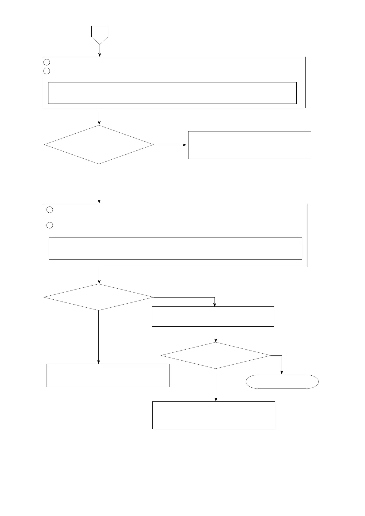
Set the connecting range to DC ・ V for the measuring instrument such as tester
and so on.
1
Remove the connecting cable for sensor from rear panel terminal board.
2
Measure the voltage between the terminals of A and C after shortening the terminals
between A−F and C−G on the rear panel terminal board.
The voltage between
B and D varies.
The voltage between
A and C is same as the setting
of FUNC−55.
6
Make calibration again according to
section 5. Calibration procedure.
Start measurement.
Same condition.
There may have fears that connected
sensor has broken or signal route
(signal wire) has cut off.
NO
YES
1
Connect the connecting cable for sensor with rear panel terminal board again.
(Refer to section 4. Connecting method.)
2
By checking the voltage between the terminal B and D on the rear terminal board, apply
load to the sensor.
Set the connecting range to DC ・ mV for the measuring instrument such as
tester and so on.
YES
YES
Inform Minebea about the contents of
failure and situation at site in details.
NO
NO
Inform Minebea about the contents of
failure and situation at site in details.