5 - 2
5.1 Handling Precautions
5
SETTINGS AND PROCEDURES BEFORE OPERATION
• The casing of the C Controller module is made of resin.
Do not drop it or not apply strong shock to it.
• Do not remove the printed boards of the module from the casing.
Doing so may cause a failure.
• Tighten the module fixing screws and the RS-232 cable connector mounting screw
within the following range.
* 1 The module can be easily secured to a base unit by the hook on the module top. However, it is
recommended to fix it with the module mounting screws in a place of high vibration and/or shock.
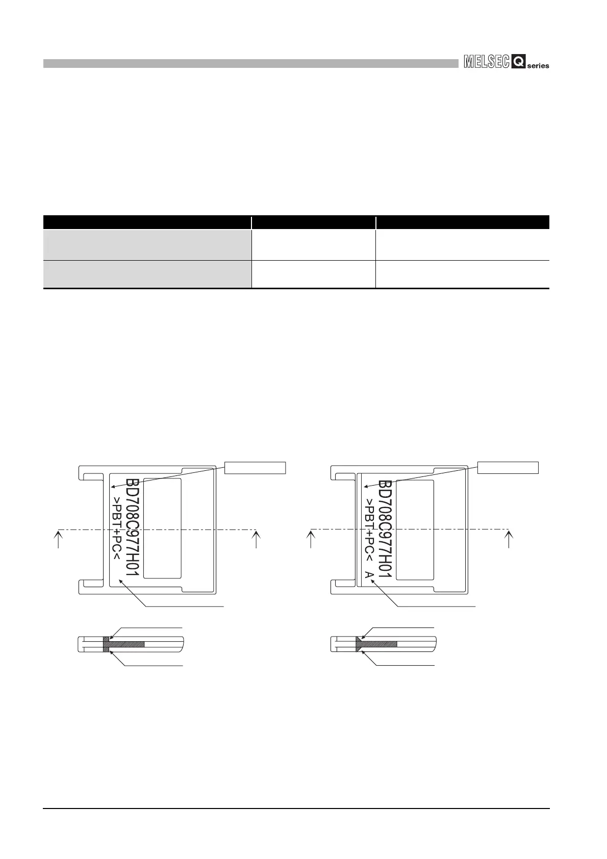
• When installing a dummy CompactFlash card to the C Controller module, use the
dummy CompactFlash card installed when shipping.
Do not use the dummy CompactFlash card that has no "A" shown in Figure 5.1 printed
to the products whose serial No. (first four digits) is "1008" or later. Failure to do so may
disable to remove the dummy CompactFlash card, resulting in damage to the
CompactFlash card slot.
A dummy CompactFlash card with "A" shown in Figure 5.2 printed is installed to the
products whose serial number (first four digits) is "1008" or later when shipping.
Table5.1 Tightening torque range
Screw location Tightening torque range Remarks
Module fixing screw (normally not required)
(M3 screw)
*1
0.36 to 0.48N•m -
RS-232 cable connector mounting screw
(M2.6 screw)
0.20 to 0.39N•m
Depth of screw hole: L=3.2mm or less
(Internal dimension from side edge)
Figure 5.1 The dummy CompactFlash card
("A" is not displayed)
Figure 5.2 The dummy CompactFlash card
("A" is displayed)
No chamfering
No chamfering
No chamfering
"A" is not displayed
Chamfering
"A" is displayed
Chamfering
Chamfering

 Loading...


