6
I/O NUMBER ASSIGNMENT
6.2 Connecting Extension Base Units and Setting No. of Stages
6 - 6
1
OVERVIEW
2
SYSTEM
CONFIGURATION
3
SPECIFICATIONS
4
FUNCTIONS
5
SETTING AND
PROCEDURES
6
I/O NUMBER
ASSIGNMENT
7
MEMORIES AND
FILES
8
INSTALLING /
UNINSTALLING
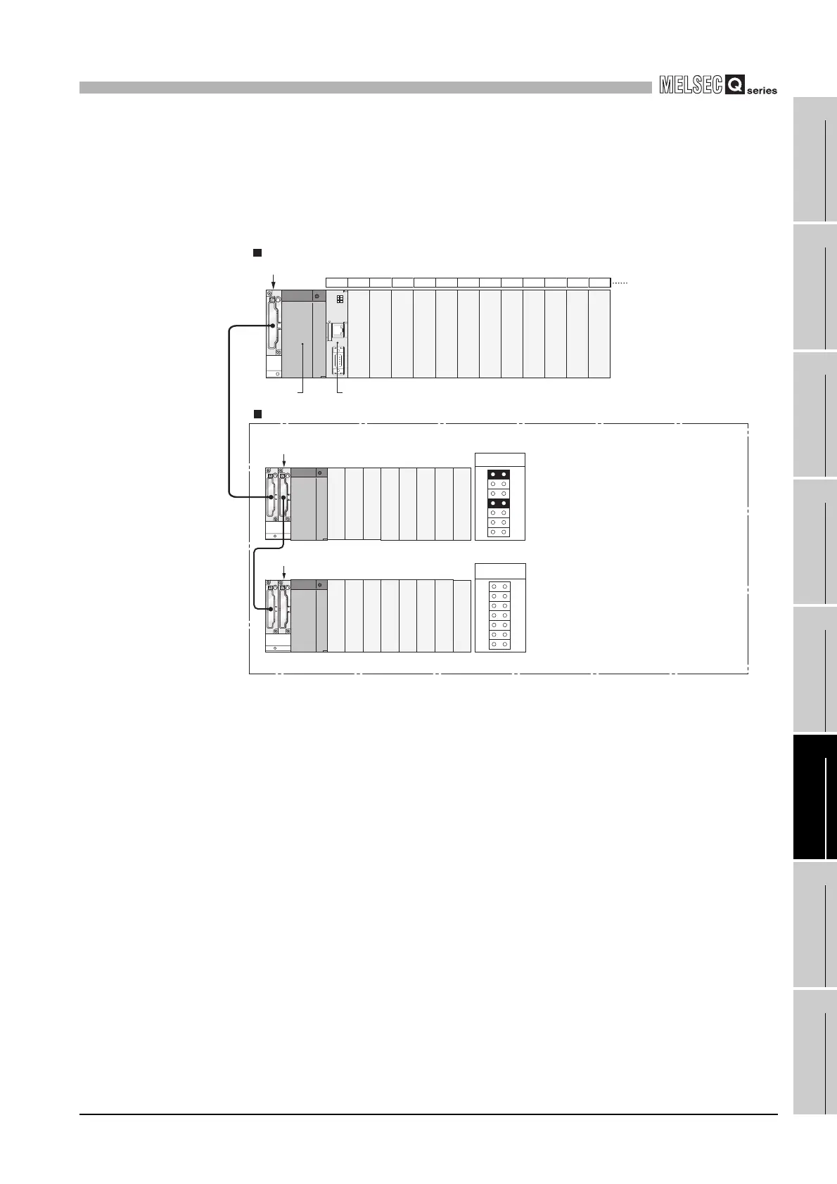
(c) When connector pins are inserted into two or more positions or no
connector pin is inserted
Extension base units cannot be used with connector pins inserted in two or more
positions.
Also, they cannot be used without connector pins being inserted.
Figure 6.5 When connector pins are inserted into two or more positions or no connector pin is inserted
C Controller module
CPU01234567891011
Q312B
Q68B
Q68B
Power supply
module
Main base unit
Extension base unit
Slot number
Extension 1
Extension 2
Connector pin must be inserted!
Connector pins must not be
inserted in 2 or more positions!

 Loading...


