18
TROUBLESHOOTING
18.3 Actions for Lit/Flashing ERR. LED
18 - 29
17
STARTING
MULTIPLE CPU
SYSTEM
18
TROUBLESHOOTING
APPENDICESINDEX
(To next page)
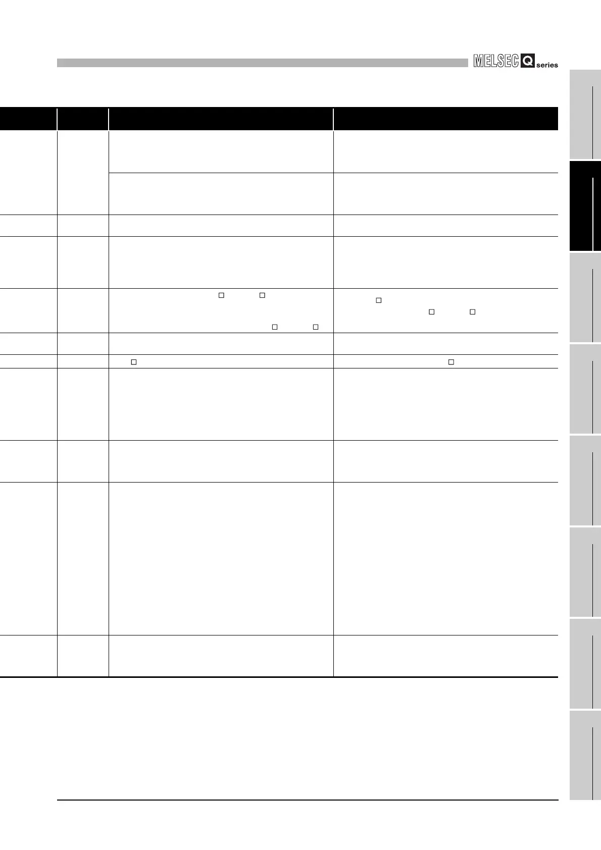
error code Error description and cause Corrective action
2106
• 5 or more MELSECNET/H modules have been installed in a whole
multiple CPU system.
• 5 or more Q series Ethernet interface modules have been installed
in a whole multiple CPU system.
• Reduce the number of MELSECNET/H modules to 4 or less in the
whole multiple CPU system.
• Reduce the number of Q series Ethernet modules to 4 or less in the
whole multiple CPU system.
• 5 or more MELSECNET/H modules have been installed.
• 5 or more Q series Ethernet interface modules have been installed.
• The same network number or same station number is duplicated in
the MELSECNET/H network system.
• Reduce the number of MELSECNET/H modules to 4 or less.
• Reduce the number of Q series Ethernet modules to 4 or less.
• Check the network numbers and station numbers.
2107
The start X/Y set in Parameter’s I/O assignment setting is overlapped
with the one for another module.
Make the Parameter’s I/O assignment setting again so that it is
consistent with the actual status of the intelligent function modules.
2108
• A network module for A2UCPU (A1SJ71LP21, A1SJ71BR11,
A1SJ71LR21, A1SJ71AP21, A1SJ71AR21, or A1SJ71AT21B) is
mounted.
• A network module for Q2AS (A1SJ71QLP21(S), A1SJ71QBR11 or
A1SJ71QLR21) is mounted.
Replace the network module with a MELSECNET/H module.
2120
• In a single CPU system, the QA B or QA1S B was used as a
base unit.
• In a multiple CPU system configuration, the C Controller module
was set as a CPU controlling modules on the QA B or QA1S B.
• Use the Q B as a base unit.
• Set the modules on the QA B or QA1S B to be controlled by the
High Performance model QCPU.
2121
The CPU module is installed to other than the CPU slot and slots 0 to
2.
Check the mounting position of the C Controller module, and mount it
to the correct slot.
2122
QA1S B is used to the main base unit. Change the main base unit to the Q B.
2124
• A module is installed to the 65th or higher slot.
• A module is installed to the slot whose number is greater than the
number of slots specified in the base assignment.
• A module is installed to the location corresponding to the I/O points
of 4,096 or greater.
• A module is installed to the slot whose assigned I/O range include
the limit of 4096.
• Remove the module installed to the 65th or later slot.
• Remove the module installed to the slot whose number is greater
than the number of slots specified in the base assignment setting.
• Remove the module installed to the location of I/O points, 4,096 or
greater.
• Replace the last module with a module whose I/O points do not
exceed 4,096.
2125
• A module that cannot be recognised has been installed.
• There was no response form the intelligent function module.
• Install an applicable module.
• The intelligent function module is faulty. Please consult your local
Mitsubishi service center or representative, explaining the details of
the problem.
2126
In a multiple CPU system, the CPU module configuration is as
described below.
• There are empty slots on the left-hand side of the CPU module.
• A CPU module other than the High Performance model QCPU is
mounted on the left-hand side of the High Performance model
QCPU.
• When CPU No.1 is the High Performance model QCPU, a CPU
module other than the C Controller module is mounted on the right-
hand side of the C Controller module.
• When CPU No.1 is the C Controller module, a programmable
controller CPU is mounted on the right-hand side of the C Controller
module.
• When CPU No.1 is the Basic model QCPU, a CPU module is
mounted on the right-hand side of the C Controller module.
Take the following actions.
Refer to Section 13.1 for the CPU module's mounting position in a
multiple CPU system.
• Eliminate any empty slot space between CPU modules by moving
the mounted modules to empty slots. (Set empty slots on the right-
hand side of the CPU modules.)
• Remove the module other than the High Performance model QCPU
mounted on the left-hand side of the High Performance model
QCPU, and move the High Performance model QCPU to the left.
• Remove the CPU module other than the C Controller module
mounted on the right-hand side of the C Controller module.
• Remove the programmable controller CPU mounted on the right-
hand side of the C Controller module.
• Remove the CPU module mounted on the right-hand side of the C
Controller module.
2150
In a multiple CPU system, the control CPU of the intelligent function
module incompatible with the multiple CPU system is set to other than
CPU No.1.
• Change the intelligent function module for the one compatible with
the multiple CPU system (function version B or later).
• Change the setting of the control CPU for the intelligent function
module incompatible with the multiple CPU system to CPU No.1.
* 2 In the "Error time operation mode" on the <<System setting>> tab of the C Controller setting utility, the CPU operation status after error
occurrence can be set to "Stop" or "Continue". (The LED display also changes according to the setting.)

 Loading...


