PN: L-MAM2-E-201
Moog Casella DM2020 Installation and Startup Guide
2.8.3 Safeguards Related to SCRF
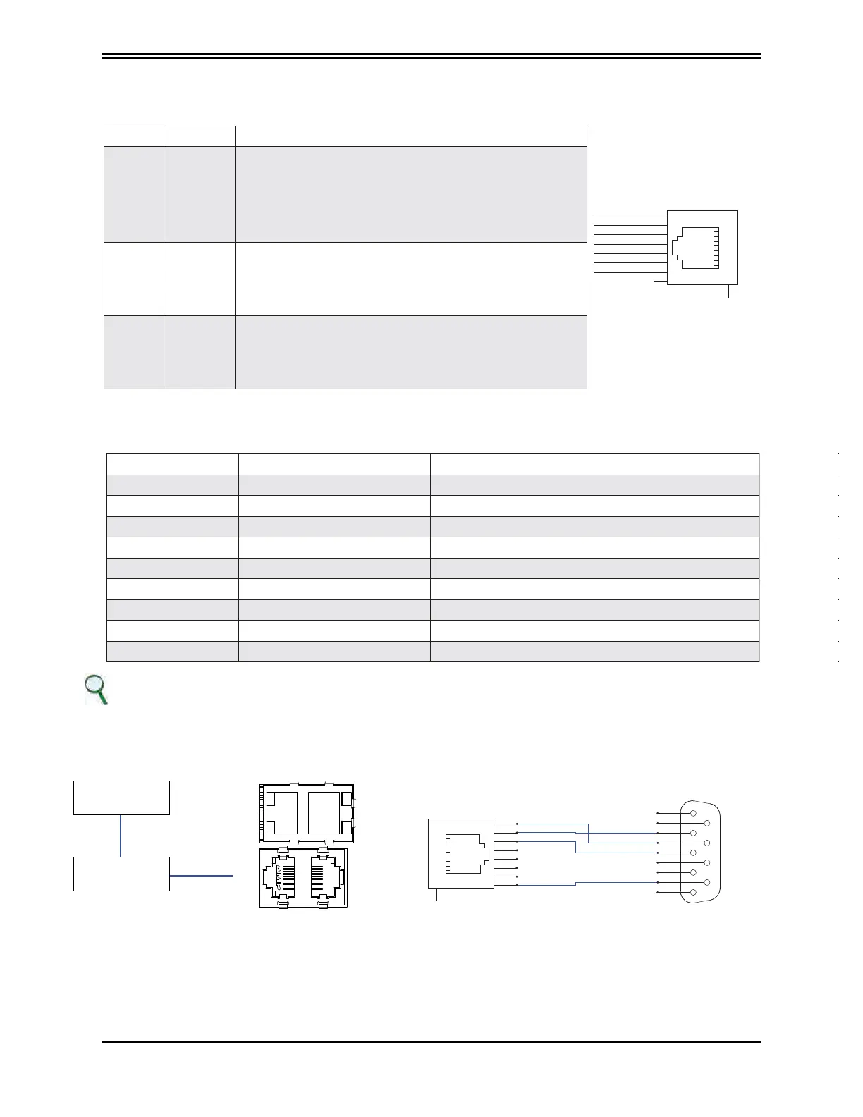
X8 (X9) connector: EtherCAT interface
The cable is a standard EtherCAT cable and the connector is an RJ45.
LED Name Description
EtherCat
TX+ 1
2
3
4
5
6
7
8
2V5
TX-
RX+
2V5
RX-
SHIELD
X8 - X9
9
SHIELD
SHIELD
X8 -
RUN
EtherCAT
run
indicator
OFF
FLASHING
FLASHING
ON
FLICKERING
Drive status is INIT
Drive status is PRE-OPERATIONAL
Drive status is SAFE-OPERATIONAL
Drive status is OPERATIONAL
Drive status is BOOTSTRAP
X8 - L/A
EtherCAT
Link/
Activity
OFF
ON
FLICKERING
The Ethernet input port is closed
The Ethernet input port is open
The Ethernet input port is open and network
activity is present
X9 - L/A
EtherCAT
Link/
Activity
OFF
ON
FLICKERING
The Ethernet input port is closed
The Ethernet input port is open
The Ethernet input port is open and network
activity is present
X10A (X10B) connector: CANOpen interface
The connector is an RJ45 and the pin is specified in the table which follows:
No. of pins Designation Function
1 Can_H CAN line positive terminal
2 Can L CAN line negative terminal
3 0 V_ Ca n CAN line 0 logic
4 Aux_Ps_Fault Signal (denied) of power supply status
5 Addr_d x DX address for internal communications
6 Ps_out Power supply command output
7 Addr_sx SX Address for internal communications
8 +5VCan CAN line power supply (supplied by power supply).
SH Shield Shield
INFORMATION
The PC-drive connection via CAN currently uses a VCI V3 model USB CAN adapter by IXXAT Automation
(www.ixxat. com); other models or devices may be added to the GUI on request.
EthetCAT
RUN
X8
X10
LNA
IN
L/A
X9
X10
LNB
OUT
L/A
Personal Computer
with
DM2020GIU.exe
USB-CAn Adapter
IXXATVCI V3
Dedicated PC-Axis connection via CAN
9
SHIELD
RJ45 Connector
Male CAN connector
CAN_
H
1 with 7 CAN_H
2 with 2 CAN_L
3 with 3 GND
8 with 9 +5
CAN
_L
0V_CAN
+5V_CAN
1
1
2
3
4
5
6
7
8
2
3
4
5
6
7
8
9
DB9
CAN RJ45 DB9 connection diagram
 Loading...
