PN: L-MAM2-E-201
Moog Casella DM2020 Installation and Startup Guide
3.3.2 Selecting a Non-Moog Motor
Digital Out 1/2 options
• Halt is active
• Stop is active
• Motor dir. clockwise
• Motor dir. counterclockwise
• Motor null speed
Digital Input options
• Drive enable
• Reference enable
• Quick stop
• Reset alarm
• Limit switch (CCW and CW)
• Position “ capture” with dedicated procedures enabled (touch probe)
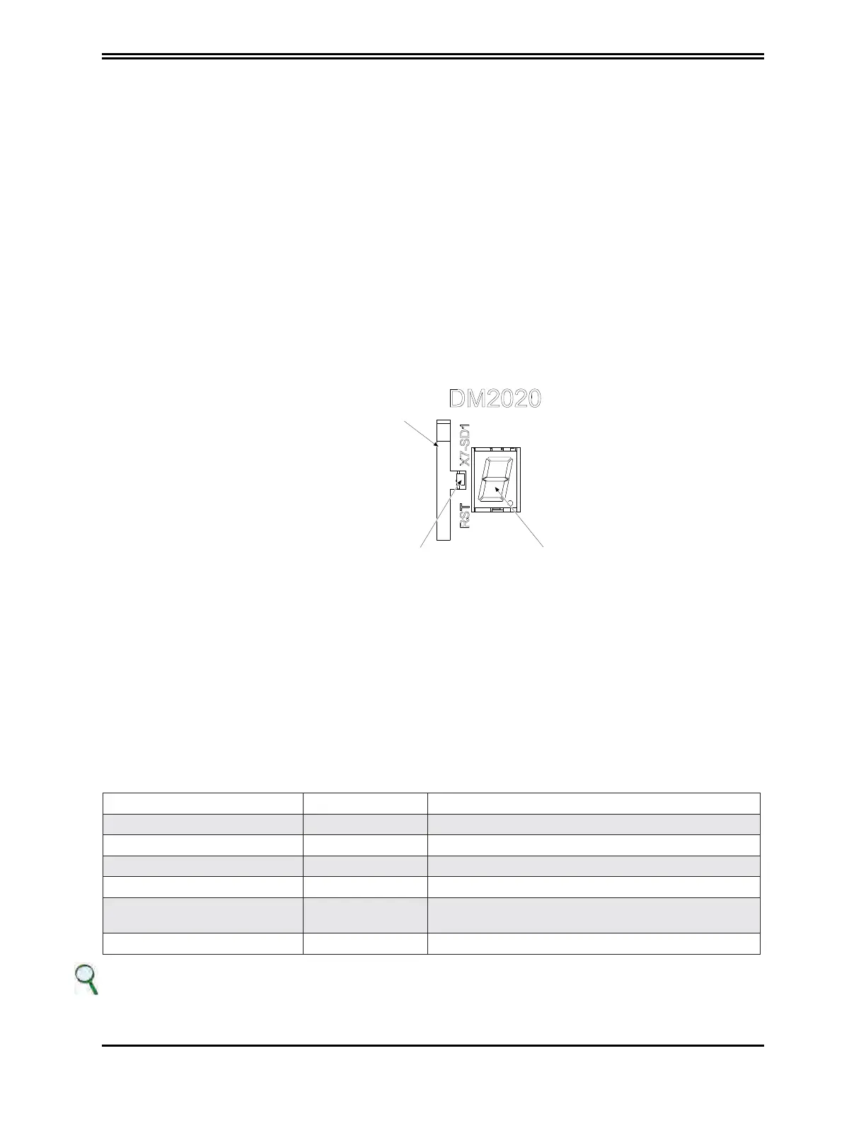
X7 (X17) connector
HOUSING
FOR MEMORY
CARD
RESET BUTTON DISPLAY IN 7 SEGMENTS
Housing for memory card
Inserting an SD card enables the information to be saved in several ways: Log iles and/or parameters.
Reset button
Situated alongside the memory card; triggers the activation of the drive control section when pressed. When
pressed and held (> 3 seconds), it triggers access to the drive's Boot routine and the possibility to download a
different version of the control SW via the GUI.
LED display in 7 segments
Indicates the status of the axis after the addition of the 24 V auxiliary.
The meaning of messages is shown in the table below:
Display message Status ID Notes
I Setup The drive has completed setup
S Ready The drive is ready to be enabled
E Enabled The drive is controlling the motor
F Fault The drive has an alarm status
8 flashing Boot via Serial
The drive is being programmed via the RS 232 serial
line
b flashing Boot via EtherCAT The drive is being programmed via EtherCAT
INFORMATION
If the operating mode chosen is “Analogue”, in the event of a fault, a two-digit code will be displayed after the letter F
which will identify the alarm. The codes can be consulted in section “6.3.1. Viewing alarms in the “Analogue” operating
m
ode”.
 Loading...
