PN: L-MAM2-E-201
Moog Casella DM2020 Installation and Startup Guide
3.3.2 Selecting a Non-Moog Motor
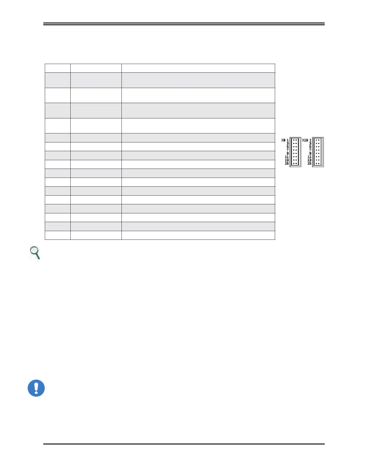
X6, X16 connector
Analogue and digital I/Os are present:
PIN Designation Function
1 IN AN 1 +
Positive analogue input 1, 12-bit resolution, sampling 3.9 us
(256 kHz)
2 IN AN 1 -
Negative analogue input 11, 12-bit resolution, sampling 3.9
us (256 kHz)
3 IN AN 2 +
Positive analogue input 2, 12-bit resolution, sampling 3.9 us
(256 kHz)
4 IN AN 2 -
Negative analogue input 2, 12-bit resolution, sampling 3.9 us
(256 kHz)
5 OUT AN 1 Analogue output 1, 12-bit resolution
6 OUT AN 2 Analogue output 2, 12-bit resolution
7 +24 VOLT 24 V input for power supply to digital outputs
8 0 VOLT Common earth of the digital I/Os
9 OUT DIG 1 Digital output 1, opto-isolated
10 OUT DIG 2 Digital output 2, opto-isolated
11 DRIVE_OK Contact drive OK
12 DRIVE_OK Contact drive OK
13 IN DIG 1 Digital input 1, fast, opto-isolated
14 IN DIG 2 Digital input 2, fast, opto-isolated
15 RESTART Module reset
16 0 VOLT Common earth of analogue inputs
INFORMATION
The two earths on pins 8 and 16 are separated in order to increase the electric noise rejection from the wiring
Programming of digital and analogue I/O (connector X6):
Analogue Input 1 and 2 options
• Torque reference
• Velocity reference
• Current limitation (maximum torque
deliverable)
Analogue Out 1 and 2 options
• Current reference
• Actual speed
• Phase current (measured on the U and V phases).
• Speed error
• Position error
CAUTION
Analogue inputs are referred to 0 Volt analogue earth on pin 16; the 0 Volt digital earth is used for the power
supply for
the
digital outputs
Note on analogue inputs:
 Loading...
