MOOR INSTRUMENTS moorLDI2 RESEARCH USER MANUAL
14
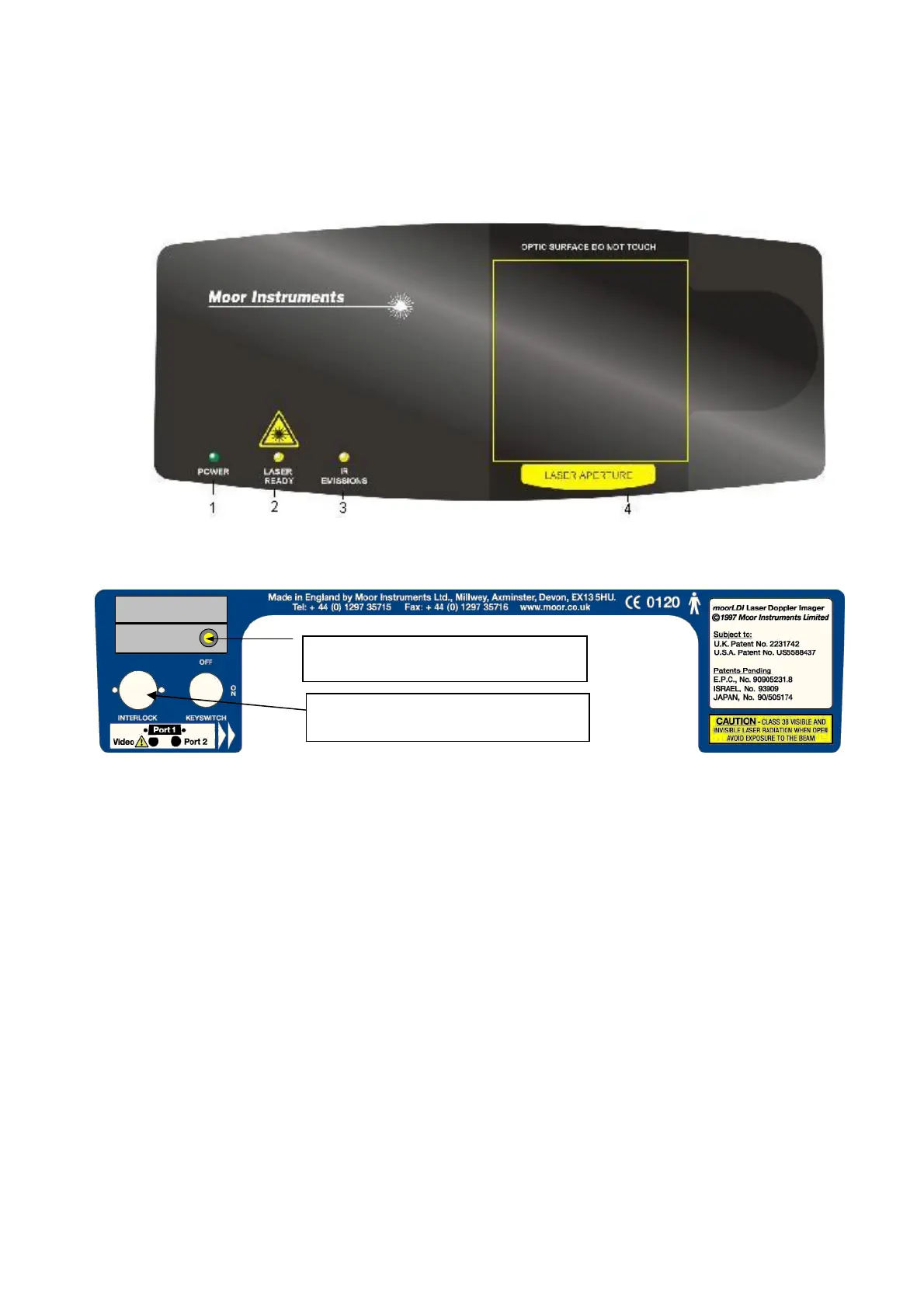
Figures 2F and 2G show the layout of the front panel and back panel labels of the moorLDI2 single
infrared wavelength scanner units.
moorLDI2-IR and moorLDI2-HIR
FIGURE 2F - FRONT PANEL OF THE moorLDI2 INFRARED SCANNER UNIT
(* Interlock – see section 1.2.2.7 . This connector socket and plug are not required for class 3R laser
systems and are not present in the latest model of moorLDI2-IR imagers.)
FIGURE 2G - BACK PANEL LABELS OF THE moorLDI2 INFRARED SCANNER UNIT
DATE OF MANUFACTURE
2006
MLDI S/N
5***
MODEL
MOORLDI2-BI IR
IR EMISSION
1 2
Infrared Emission Warning LED
1. Interlock* 2. Key Switch


 To Next Page