The Computer
5-108 Manual # 42-02-1P21
Duplexing
A great advantage of the Motion 2000 is how easily it can be duplexed. Because the duplexing
logic is completely internal to the computers, it requires only a connecting cable and the selec-
tion of the Duplex option (see “SIMPLEX / LOCAL OR DUPLEX?” on page 5-17). The duplexing
logic provides for proper assignment of hall calls to cars and increases efficiency and decreases
waiting time.
Dispatching Algorithm
The dispatching algorithm for assigning hall calls will be real-time based on estimated time of
arrival (ETA). In calculating the estimated time of arrival for each elevator, the dispatcher will
consider, but not be limited to, the location of each elevator, the direction of travel, the existing
hall call and car call demand, door time, flight time, lobby removal time penalty and coinci-
dence call.
Hardware Connections
There are two critical items in duplexing hardware: Proper grounding between the two control-
ler subplates and proper installation of the duplexing cable. The hall calls will be connected to
both cars simultaneously. Once in a duplex configuration, either of the two controllers can
become the dispatcher of hall calls. The controller that assumes the dispatching duty on power
up remains the dispatching processor until it is taken out of service. If, for any reason, the com-
munication link between the two controllers does not function, each car will respond to the reg-
istered hall calls independently.
Troubleshooting
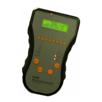
In a duplexing configuration, the controller that assumes dispatching duty is identified by the
letter D in the upper left corner of the LCD display. The other car is identified by the letter S
(slave), in the upper left corner of the LCD. If the upper left-hand corner of the LCD is blank
(neither the D nor the S is displayed), the cars are not communicating.
Power Phasing
When cars are paired for duplex operation, input power phasing to the two must match.
1. Connect a multimeter, set for AC voltage, between a 2 Bus terminal on one controller
and a 2 Bus terminal on the second controller. If the meter reads close to zero (0) volts,
the two are in phase. If not:
• Swap two of the L1/L2/L3 inputs on one car and repeat step 1.

 Loading...