Startup - Inspection Operation
3-20 Manual # 42-02-1P21
Hoistway Learn Operation
After installing the leveling and terminal magnets and setting step up/step down distances, you
will need to perform a learn operation to learn floor and “switch” positions. If floor level mag-
nets have not been positioned accurately enough, any offset can be adjusted in software (+/- 1
inch).
1. Place the car on Inspection operation.
2. Move the car to the bottom terminal.
3. Set the F6 function switch in the UP/ON position.
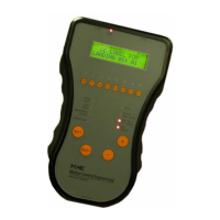
4. The LCD will display HOISTWAY LEARN, PRESS S.
5. Press S to initiate learn.
6. Place car on TEST mode. Shut off INSPECTION. Follow instructions on the LCD.
Synopsis As you follow the instructions on the LCD, the car will first travel down to the
bottom terminal then move up to locate the center of the door zone magnet. From the bottom
terminal, the car will move up the hoistway finding each door zone and indicating the height in
inches of each door zone magnet center (Front and/or Rear as appropriate). Upon reaching the
top terminal, the LCD will report hoistway information stored and offer the option to press N if
you are Done or S if you want to restart the learn operation.
7. Press N when hoistway learn reports complete to exit the operation.
8. Place F6 in the Down position.
Adjusting Floor Heights
Motion 2000 allows the door zone heights to be individually adjusted in 0.10 inch increments
to compensate for magnet placement irregularity up to a maximum +/- 0.9 inches for LS-
EDGE. Stored floor heights may be accessed through the F7 menu (first 32 parameters) and the
height of each floor individually adjusted at any time.
1. Place the car on Inspection, enter the F7 menu (F7 up, all other switches down).
2. Press N to advance to the desired parameter.
3. Use “+” or “-” buttons to adjust the height of the floor.
4. Place F7 in the down position.
Initial Stepping Distances
The initial settings for the run up and run down stepping distances were set at the factory.
When running up to a floor, the floors Step Up position forces the elevator to drop high speed.
When running down to a floor, the floors Step Dn position performs the same function. These
settings can be verified or adjusted through the F7 parameters #209 + Step Dn“x” and 210 +
Step Up“x”.
Door Position Monitor Switch (If used)
If you are in a jurisdiction where ASME A17.1 - 1996 or later is being enforced, Door Position
Monitor switch(es) connected to the DPM and/or DPMR inputs must be added to monitor the
position of the closed doors. This must be a separate physical limit switch that makes up
approximately 1 to 2 inches before the doors lock. Please refer to the DOOR POSITION MONI-
TOR and DOOR CLOSE LIMITS options on page 5-55.

 Loading...