The Computer
5-6 Manual # 42-02-1P21
Diagnostic Mode
Onboard Diagnostics are designed to aid in evaluating the status of the control system. Onboard
Diagnostics help to pinpoint the cause of elevator malfunctions.
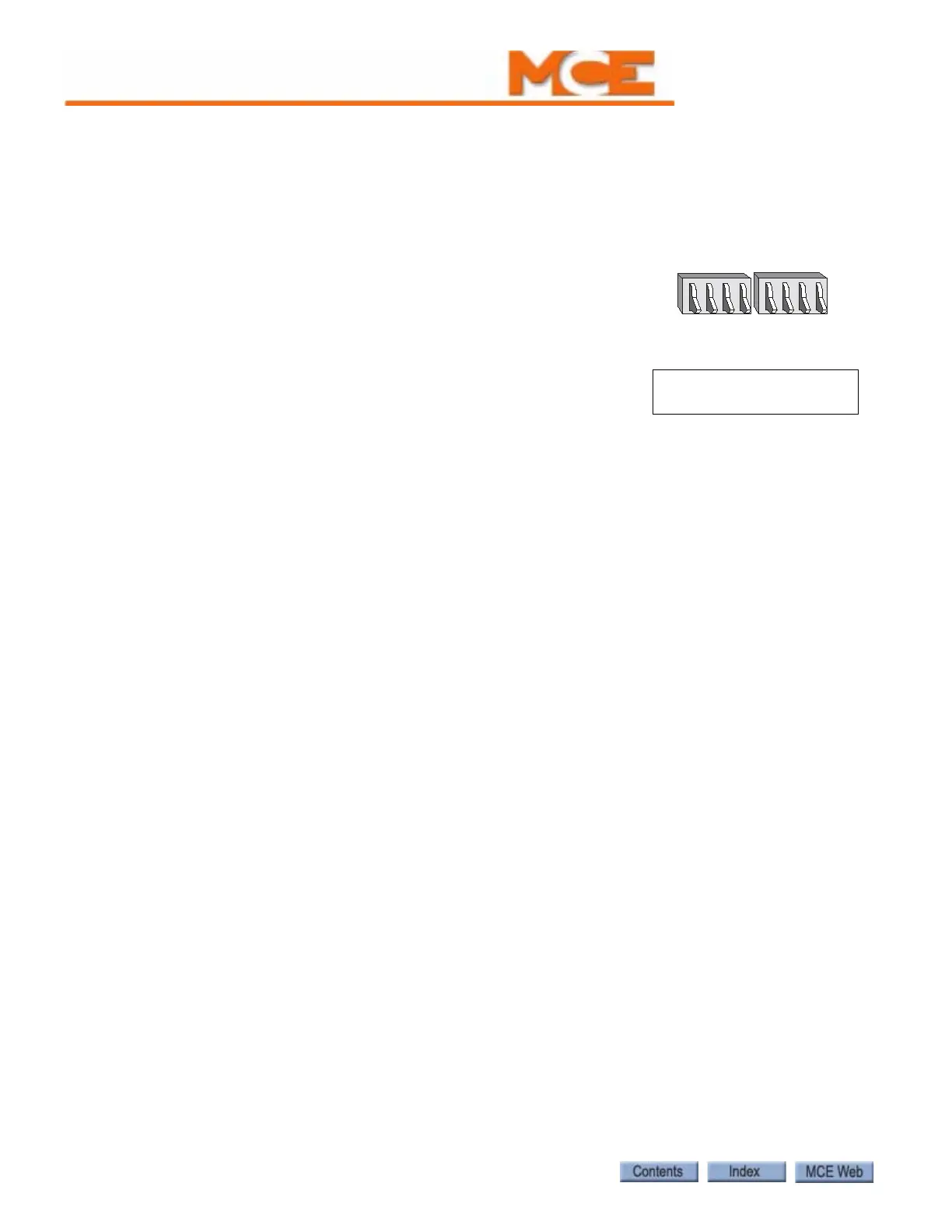
Getting into Diagnostic Mode
Diagnostic mode is initiated by placing Function Switches F1 - F8
in the down position. A description of the LCD display format and
the function of the N, S, +, and - push buttons during Diagnostic
mode follows.
Function of N Push Button
The N push button selects the digit of the computer memory
address, which is displayed on the second line of the LCD. For
example, for the following display, pressing the N push button
once will cause the 2 of the address 20 to begin blinking. By continuing to press the N push but-
ton, the 0 of address 20 will begin to blink. The cycle will continue while the N push button is
being pressed. Once the digit to be changed is blinking, the address can then be modified using
the + and – push buttons as described below.
The data (8 digits) that corresponds to the memory address, is displayed to the right of the
address (see “Computer Internal Memory” on page 5-7). This display will change as the memory
address changes.
Function of S Push Button
The S push button ends the ability to change the address by stopping the digit from blinking. If
the S push button is not pressed, the selected digit will stop blinking automatically after a
period of about 20 seconds.
Function of + Push Button
The + push button modifies the digit of the computer memory address selected by the N push-
button. If the + push button is pressed, the selected digit is incremented by one. The data dis-
play will also change as the address changes. For example, if the 0 of the address 20 is blinking,
pressing the + push button once will change the address from 20 to 21. Pressing the + push but-
ton several more times will change the address to 22, 23, 24, etc., up to 2F and then back to 20
again. If the 2 of address 20 is blinking, pressing the + push button once will change the address
from 20 to 30. Pressing the + push button several more times will change the address to 40, 50,
60, etc., up to F0. Once the address has reached F0, pressing the + push button will cause the
address to begin back at 00.
Function of - Push Button
The – push button also modifies the digit of the computer memory address selected by the N
push button. If the – push button is pressed, the selected digit is decremented by one. The data
display will also change as the address changes. For example: If the 0 of address 20 is blinking,
pressing the – push button once will change the address from 20 to 2F. Pressing the – push but-
ton several more times will change the address to 2E, 2D, 2C, etc., back to 20 again. If the 2 in
the address 20 is blinking, pressing the – push button once will change the address from 20 to
10. Pressing the – push button several more times will change the address to 00, F0, E0, etc.,
back to 00. Once the address has reached 00, pressing the – push button will cause the address
to start over at F0.
FUNCTION SWITCHES
F8 F7 F6 F5 F4 F3 F2 F1
Diagnostic Mode
NORMAL OPERATION
PI 8 2O:1O11OO11