Troubleshooting
6-50 Manual # 42-02-1P21
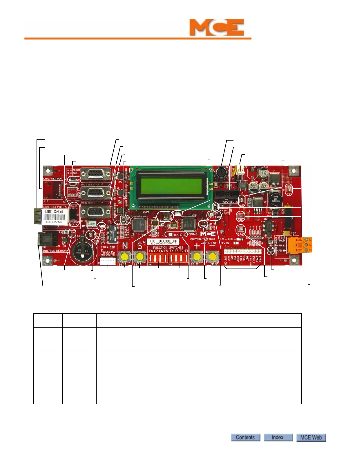
HC-MPU Main Processor Board
The HC-MPU board performs control data processing and is responsible for:
•Car operation
• Car communication
• Programming and diagnostics
• Redundancy cycle testing
• System software validation
•Duplexing
Figure 6.5 HC-MPU Main Processor Unit Board
Table 6.11 HC-MPU Board Jumpers
Jumper Setting Description
JP1 A Selects voltage for LCD. A = 5V, B = 3.3V
JP2 - CPU A hard reset. No jumper provided, only required for 2K testing.
JP3 Closed External CAN network termination.
JP4 Open Internal CAN network termination
JP5 A Ethernet Port B (not currently used)
JP6 Open JTAG Debug Jumper. Closed = debug mode.
JP7 - CPU B hard reset. No jumper provided, only required for 2K testing.
S6
LCD Display
M1: Ethernet Port A
J5: Internal CAN connection
J6: CPU B Debug
J2: Keyboard Port
J4:External CAN Port
SW1
Indicators
J7: RS232 Port B
J3: RS232 Port A
JP5
J10: Ethernet Port B
S1: RSTA
S4
J1
SW2
S5
S3SW3
JP2
TP GND
TP +5V
TP GND
TP +3.3V
TP +25V
JP1
CPU B ON LED
CPU A ON LED
JP7
JP4
JP3
J8: CPU-B JTAG
J9: 16VAC input
S2: RSTB
JP6