PC Board Quick References
6-51
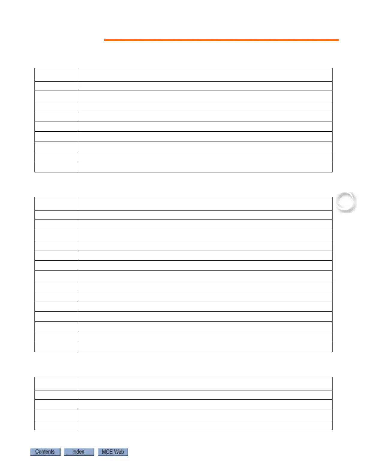
Table 6.12 HC-MPU Board Switches
Switches Description
S1 RSTA: Reset CPU A
S2 RSTB: Reset CPU B
S3 “-” minus push button
S4 “S” push button
S5 “+” plus push button
S6 “N” push button
SW1 Port Selection: RS232 Port A / Ethernet Port A
SW2 DIP Function switches F5 through F8
SW3 DIP Function switches F1 though F4
Table 6.13 HC-MPU Board Indicators
Indicators Description
CPU A ON CPU A is executing its program
CPU B ON CPU B is executing its program
LED2 Reserved
LED1 Reserved
FAULT A fault has been detected.
CPU ON All processors are fully functional.
MLT Motor/Valve Limit Timer: The motor/valve limit timer has elapsed.
TOS Timed Out of Service: The TOS timer has elapsed and the car is out of service.
FIRE Fire Service: The car is on fire service operation.
INSP Inspection: The car is on inspection operation.
IND Independent Service: The car is on independent service.
HS High Speed: The car is running at high speed.
DLK Doors Locked: The door lock contacts are made.
SAF ON Safety On: The safety circuit is made.
Table 6.14 HC-MPU Board Test Points
Test Points Description
GND 0V
+3.3V +3.3 Vdc measured between this test point and TP GND.
+5V +5 Vdc measured between this test point and TP GND.
+25V unregulated 25Vdc from the HC-CHP board