Installation
2-6 Manual # 42-02-1P21
Nomenclature
A listing of PC boards and their designator numbers plus other schematic symbols used in the
wiring prints can be found at the beginning of the Job Prints and in the Component Nomencla-
ture table below.
• Become familiar with the “Elevator Car Wiring Print” drawing number -1.
• Become familiar with the “Elevator Hoistway Wiring Print” drawing number -2.
• Become familiar with page -2DI of the job prints for duplex interconnect wiring if this
application is duplexed.
• Review any additional wiring diagrams and details.
• The remainder of the job prints are detailed drawings of the Motion 2000 Hydraulic Con-
trol system.
• A specific part of a schematic may be referenced by the Area Number, which is found at the
left-hand margin of the schematic.
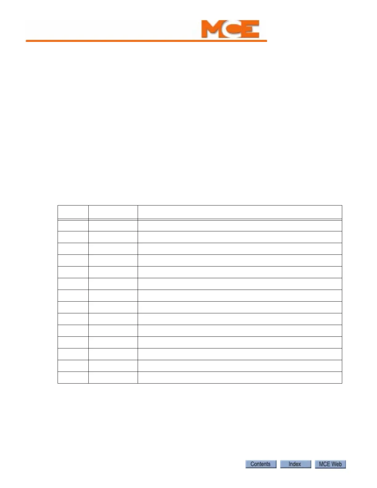
The following table lists MCE part numbers and provides a brief description for each. Your
installation may not use all boards listed.
Table 2.1 Component Nomenclature
Symbol Component Description
10 HC-DB-MOD Front G. A. L. MOD Door Interface Board
11 HC-DB-MOD-R Rear G. A. L. MOD Door Interface Board
32 HC-OA Output Adaptor Board
44 HC-GB Gong Board
45 HC-GB Additional Gong Board
70 HC-CTL-2 Controller Board for Motion 2000/4000
72 HC-DVR Hydraulic Driver board for Motion 2000
73 HC-UIO Universal I/O Board for Motion 2000/4000
75 HC-CHP CAN HUB and Power Board for Motion 2000/4000
76 HC-MPU Main Processor Board for Motion 2000/4000
ICE-COP-2 Car panel interface board
MC-CPI Car Panel Interface Board
MC-LSI Landing System Interface Board
SC-3HN Serial Hall Call Node Board