Installation Considerations
2-5
• Jumper the “N” stud on the line filter to the line filter frame.
• Continuous wire from the load reactor frame to the single-point ground stud.
• Continuous wire from the drive frame ground stud to the single-point ground stud.
Recommended Tools and Test Equipment
For proper installation, use the following tools and test equipment:
• A digital multimeter, Fluke series 75, 76, 77 or equivalent
• A hand-held tachometer
•A clamp-on AC ammeter
• Hand-held radios
•A telephone
•Test weights
• Pressure gauge
• Soldering tools, a flashlight and an MCE screwdriver (provided with controller).
Wiring Prints
Become familiar with the following information as well as the wiring prints provided with this
control system.
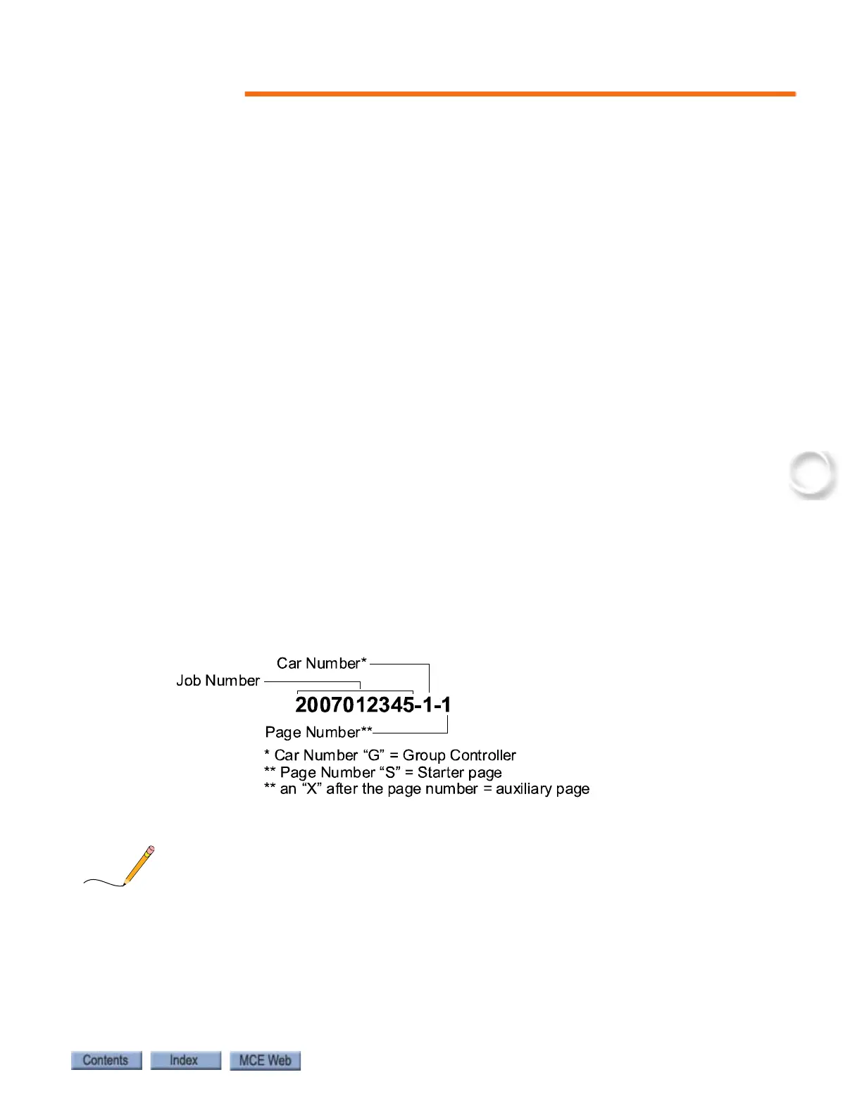
Drawing Number Format
Each print has a drawing number indicated in the title block. The drawing number is com-
prised of the job number, car number and page number (see example). In this manual the draw-
ings will often be referred to by the last digit of the drawing number (page number). The
following is the drawing number format currently in use.
Drawing Name: Some drawings have a drawing name directly above the title block or at the
top of the drawing. The drawing name may be used to refer to a particular drawing.