PC Board Quick References
6-39
Indicators
• PWR ON: +5V indicator.
• CPU ON: LED on indicates that the on-board microcontroller is functional.
Switches
• SW1: DIP switches (see SW1 DIP Switch Settings below).
• RST: microcontroller reset button.
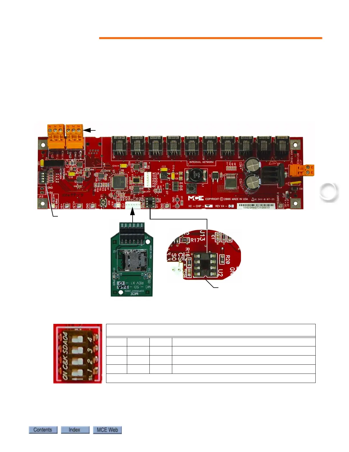
Figure 6.2 Upgrading Motion 2000 Firmware
SW1 DIP Switch Settings
DIP 4 Sets the communication baud rate for the External CAN bus
(Off = 125 kbs, On = 250 kbs).
DO NOT change this switch setting.
SW1 DIP Switch Settings
DIP 1 DIP 2 DIP 3 Description
Off Off Off Normal boot up (bypasses firmware update)
On On On Updates firmware different from EEPROM or SD card
On On Off Forced update (fixes corrupted software)
On = switch left, Off = switch right
Insert EEPROM with
notch facing this side
SW1 Switches
Update firmware using EEPROMs
(see Instruction 42-IS-0157)
Update firmware using SD Card
(see Instruction 42-IS-0176)
J16, J17, External Network connections