Diagnostic Mode
5-9
Troubleshooting Using the Computer's Internal Memory
Examining the computer memory (as in the example above) is a useful step in troubleshooting
elevator problems. It is possible to find out if the controller is receiving input signals correctly
and if it is sending out the proper output signals. It is also possible to look up each of the com-
puter output and input signals shown in the Job Prints.
The following example illustrates how to use Table 5.3 on page 8 and Table 5.4 on page 9 to
check a signal in the computer internal memory.
Example problem: the photo eye will not cause the doors to reopen.
1. Look at Table 5.4 on page 9. Find the abbreviation or mnemonic for Photo Eye input.
The table shows that the mnemonic for Photo Eye input is PHE and provides an Address
(20) and Position (7) for the signal. This will show where to look for the signal on
Table 5.3 on page 8 and on the computer display.
2. Notice on Table 5.3 on page 8 that PHE is indeed in position 7 on row 20.
3. Now that the address and position have been determined,
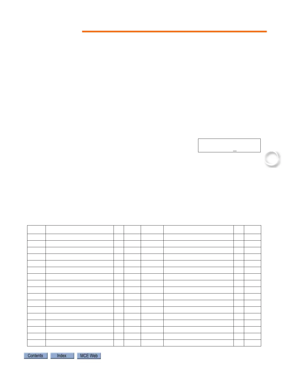
look up the PHE signal on the computer. First, change
the address on the display to address 20. Then, look at
data bit number 7 (from the right), which is underlined in the graphic:
This digit represents the computer's interpretation of the PHE signal. If the digit is 1, the com-
puter thinks that the PHE signal is ON. If the digit is 0 (as shown above), the computer thinks
that the PHE signal is OFF.
This information can be used to find the source of the problem. The diagnostic display will show
that the PHE input is ON when an obstruction is present which should interrupt the photo eye
beam. If this is the case, checking the voltage present on the PHE terminal will show if the prob-
lem is inside or outside the controller.
Table 5.4 Alphabetized Flags/Variables and Their Locations
FLAG Definition Add
Position
FLAG Definition Add
Position
ALV Other car alive output 31 5 FRS Fire phase 1 input 24 5
API Alternate Parking Input 33 8 FRSS Fire phase 1 flag 2D 3
AUTO Emergency power auto output 31 3 FWI Fire warning indicator output 25 2
BFD Bottom floor demand flag 2E 5 GED Gong enable down output 20 1
CC Car call flag 21 5 GEDR Gong enable down output (rear) 10 1
CCA Car call above flag 2A 1 GEU Gong enable up output 20 2
CCB Car call below flag 2A 5 GEUR Gong enable up output (rear) 10 2
CCC Car call cancel input 38 6 GHT Gong hold timer flag 22 4
CCD Car call disconnect flag 2C 3 GHTR Gong hold timer flag (rear) 12 4
CCH Car call hold 26 5 GTDE Gong timer down enable 26 2
CCR Car call flag (rear) 11 5 GTUE Gong timer up enable 26 1
CCT Car call time flag 22 2 H High speed output 2B 4
CCTR Car call time flag (rear) 12 2 HCDX Hall call disconnect flag 2C 4
CD Car done flag 2F 4 HCR Hall call reject flag 2C 5
CNFG Configuration error flag 38 5 HCT Hall call door time flag 22 3
CSB Car stop switch bypass 23 5 HCTR Hall call door time flag (rear) 12 3
CSBR Car stop switch bypass (rear) 13 5 HD High speed delay flag 27 8
D NORMAL OPERATI
PI 8 2O:1O
11OOOO