The Computer
5-2 Manual # 42-02-1P21
The HC-MPU Main Processor Unit
The computer on the Motion 2000 Hydraulic Elevator Controller has been designed for easy
communication between the mechanic and the controller and between the controller and other
computers or data terminals. The computer is used for diagnostic troubleshooting and for pro-
gramming the controller.
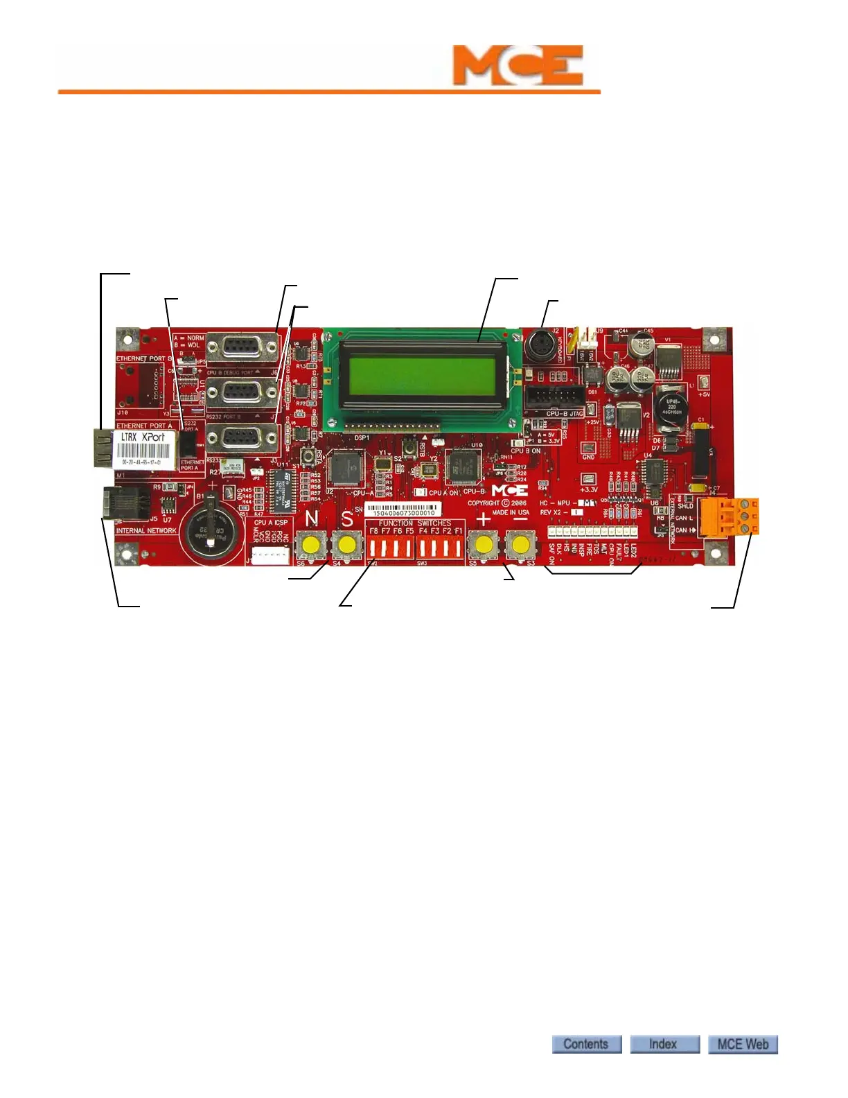
Figure 5.1 HC-MPU Main Processor Unit
Figure 5.1 shows the indicators, push buttons and terminals on the main processor unit.
Indicators
CPU-A, CPU-B When steadily illuminated, this light shows that the computer is func-
tioning normally and completing its program loop successfully. Pressing the COMPUTER
RESET button will cause the COMPUTER ON light to turn OFF and the light will stay OFF
while the RESET button is depressed. The computer is equipped with a watchdog feature that
will shut down the controller if the program loop cannot be completed (software system fail-
ure). If the COMPUTER ON light is OFF or flashing continuously, it means that the computer
board is malfunctioning.
Diagnostics LCD Display The 32-character LCD (Liquid Crystal Display) displays
various information depending on the positions of the F1-F8 switches. Diagnostic mode is
accessed when all of the switches are in the down position. The LCD display shows an elevator
status message, the car position, the contents of the computer's internal memory and communi-
cation status.
Status Indicators These lights show the status of the elevator. Table 5.1 shows a list of
these lights and their meanings.
N, S push buttons
Function Switches
F1 through F8
LCD Display
Ethernet Port
Internal CAN connection
Monitor Port
Keyboard Port
External CAN Port
Port Selector
Switch
Indicators
RS232 Ports
+, - push buttons