Troubleshooting
6-38 Manual # 42-02-1P21
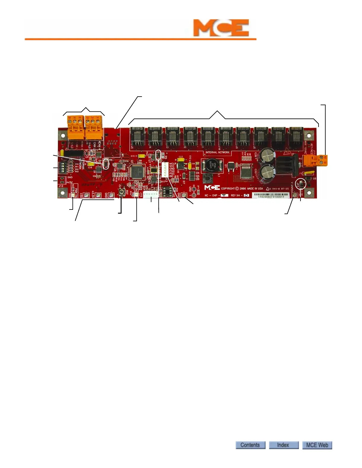
HC-CHP CAN Hub and Power Supply Board
This board provides 5-volt, 4-amp DC power for digital integrated circuits throughout the con-
troller. It also provides a central connection point for the Controller Area Network (CAN).i
Figure 6.1 HC-CHP CAN Hub and Power Supply Board
Connectors
• J1 - J10: Internal network connections - to boards inside the controller cabinet.
• J11: Low voltage AC input - 16V1/16V2, maximum 18Vrms.
• J12: optional +5Vdc output.
• J13: In-circuit serial programming port for microcontroller.
• J15: Connector used to interface with external serial flash memory.
• J16, J17: External network connections - to boards or equipment outside the controller
cabinet.
• M1: Optional Ethernet connection.
Jumpers
• JP1: Internal CAN bus termination resistor - always closed.
• JP2: External CAN bus termination resistor - always closed.
• JP3: AC or DC voltage monitor. Always set to position A to monitor the loss of AC voltage.
Test Points
• +5V: +5Vdc measured between this test point and TP GND.
• +3.5V: +3.3Vdc measured between this test point and TP GND.
•GND: 0V.
•V UNREG: 24V A20% measured between this test point and TP GND.
J11: AC input
18 Vrms max.
J1 - J10: Internal Network connections
J16, J17 External
Network connections
M1:Optional Ethernet connection
SW1
J12
PWR ON LED
Test Points
+5V, +3.3V, GND
RST button
CPU ON LED
J15
TP GND
JP2
J13
JP3
JP1
TP V UNREG