The HC-MPU Main Processor Unit
5-3
Switches, Buttons & Adjustments
Function Switches F1 - F8 The function switches are used to select the Main Com-
puter’s operating and programming modes as indicated in the following table.
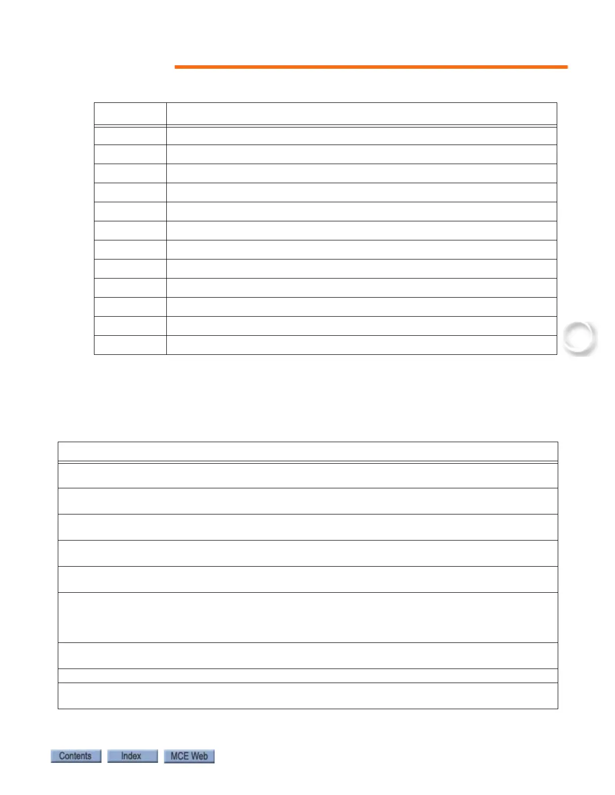
Table 5.1 Status Indicators
Indicator Description
SAF ON Safety On - Safety circuit is made
DLK Doors Locked - Door lock contacts are made
HS High Speed - The elevator is running at high speed
IND Independent Service - The elevator is on independent service
INSP Inspection / Access - The elevator is on cartop inspection or hoistway access
FIRE Fire Service - The elevator is on fire service operation
TOS Timed Out of Service - The elevator has been timed out of service
MLT Motor/Valve Limit Timer - The motor/valve limit timer has elapsed
CPU ON Computer On - The MC-MPU processors are functioning properly
FAULT Fault - A fault condition exists.
LED1 Reserved
LED2 Reserved
Table 5.2 Function Switches
Description
All OFF = Diagnostic Mode: Use for diagnosing and troubleshooting system problems (see
“Diagnostic Mode” on page 5-6).
F1 ON = Program Mode: Use to view and change the settings of parameters and programma-
ble options (see “F1: Program Mode” on page 5-14).
F2 ON = External Memory Mode: Use to diagnose problems by viewing external memory
flags (see “F2: External Memory Mode” on page 5-56).
F3 ON = System Mode: Use to program System functions, e.g. elevator security and load
weigher settings (see “F3: System Mode” on page 5-60).
F4 ON = Messages and Floor Labels: Use to program the CE fixture displays (see “F4: Mes-
sages and Floor Labels” on page 5-67).
F5 ON = Controller Utilities Menu/Monitoring and Reporting Menu: Use to register front
and/or rear car calls, set the controller’s date and time, view the event log, CAN bus data and
Monitoring and Reporting menu (see “F5: Controller Utilities/Monitoring and Reporting” on
page 5-69).
F6 ON = Hoistway learn operation menu for LS-EDGE landing system (see “F6: Hoistway
Learn Operations” on page 5-100).
F7 ON = Motion parameters adjustment (see “F7: Parameters Adjust” on page 5-101).
F8 ON = Status Display: Shows the software version, eligibility map and current load if appli-
cable (see “Status Displays” on page 5-4).