Hoistway Learn Operation
3-21
LS-EDGE Short Floors
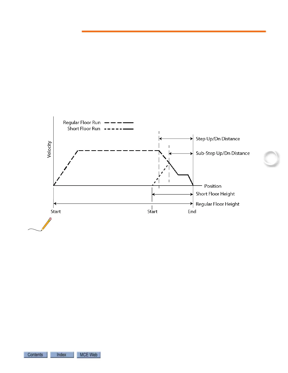
A landing that is too close to an adjacent landing such that, on a one-floor run, the car fails to
reach contract speed before reaching the stepping (Step Up/Dn) distance for the destination
floor is termed a “short floor” (see figure below). If the regular Step Up/Dn distance were used,
the car would slow to leveling speed too soon and would be required to travel at leveling speed
longer than desired. Therefore, an alternate stepping distance is provided (Sub-Step Up/Dn).
When F7 parameter #208 (Stepping System) is set to “Dual”, the Sub-Step Up/Dn distance is
used for a one floor run to any floor for which the Sub-Step Up/Dn parameters are not set to
zero (0.0). When the destination floor is a terminal landing, an additional hardware cam oper-
ated switch (Short Floor Sw) is used as backup to ensure that stepping takes place.
Figure 3.11 Regular Floor Run vs. Short Floor Run
The ideal Sub-Step Up/Dn distances must be determined by trial and error. The Short Floor
switch should be positioned a little closer to the terminal landing than the Sub-Step Up/Dn dis-
tance.
Door Zone Verification
Following the hoistway learn process, starting at the top floor, move the car down on inspection
and verify that the door zone indicators (e.g., LEDs, relays, diagnostic status, etc.) activate only
at the appropriate locations at the landings (i.e., +/- 75 mm or 3”) and nowhere else. Be sure to
check rear door zones as well, where applicable.
Permanently Attach Magnets
Once the hoistway has been successfully learned and door zone magnet placement is satisfac-
tory, you may “lock” the magnets in place by placing a drop of silicone adhesive immediately
above the top end and immediately below the bottom end of each magnet.