Troubleshooting
6-8 Manual # 42-02-1P21
CTL A or B LANDING SYSTEM COMM LOSS
Description: The HC-CTL2 board is not communicating with the landing system properly (A or B
channel lost). Before beginning troubleshooting, check all related CAN connections and connectors
carefully.
Troubleshooting:
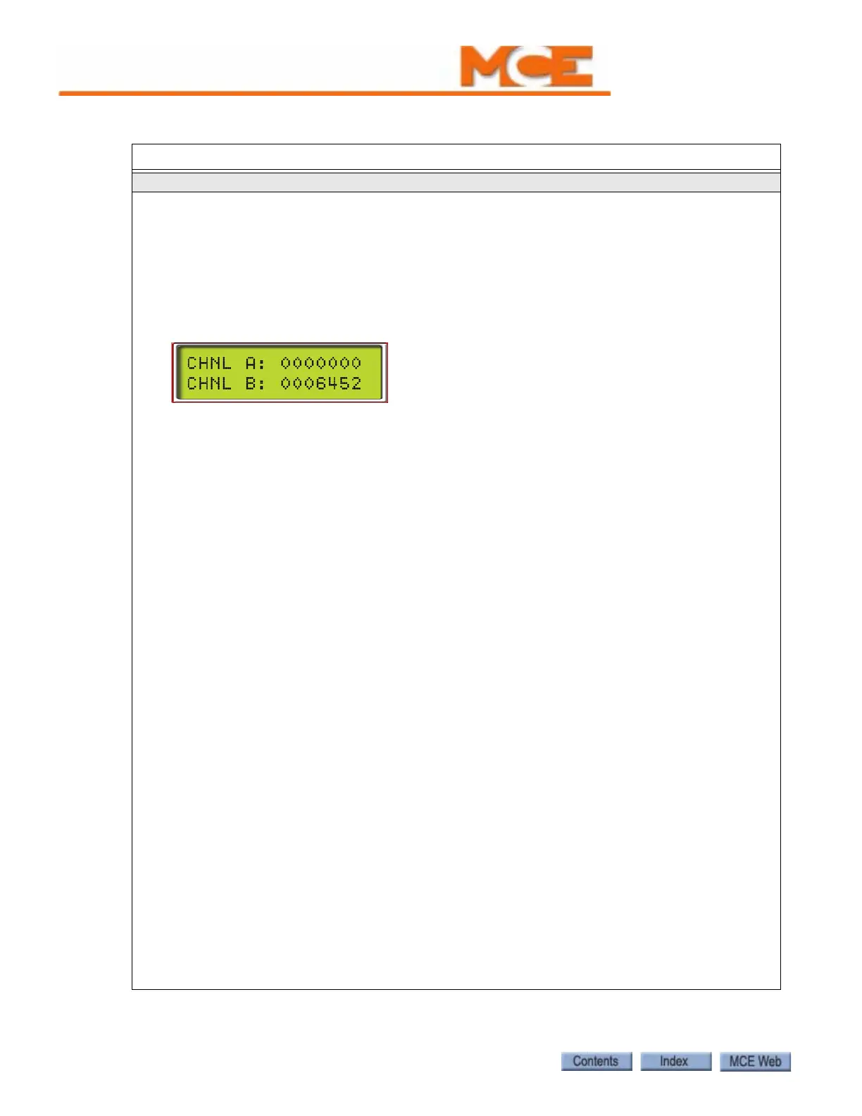
1. On the controller HC-MPU board, place F3 in the UP position. Press “N” to access the system
menu. Press “N” to advance to the Controller System Menu. Press “S” to select. Press “N” until
CHNL A and CHNL B is displayed.If a channel has failed, the position information for that chan-
nel will be missing. LS-EDGE A uses CAN 2, along with the cartop HC-UIO, MC-CPI, and ICE-
COP-2 boards. For example:
Connections Through Traveler
1. Check that the CAN connections on the HC-CTL-2 board are clean and tight.
2. On the cartop, temporarily disconnect the MACHINE ROOM / CANL2 and CANH2 wires from the
MC-LSI board. Measure the resistance between them. (All resistance measurements must be
performed with power off.) It should read about 120-ohms. Repeat for the CANL1 and CANH1
wires. They should also read about 120-ohms.
3. With power off and all CAN connections to the cartop terminated, resistance should be close to
60-ohms.
If a measured resistance is other than shown, you may have a damaged, broken, or shorted
wire in the traveler. Resolve this issue before proceeding with additional troubleshooting.
CHANNEL A
1. If the lost channel is the A (CAN 2) channel, verify cartop mounted UIO board baud rate selec-
tion is correct. Next, unplug all HC-CPI (control panel interface) and HC-UIO (universal I/O)
board CAN connections from the MC-LSI (landing system interface board) on the cartop (CAN 2
is a shared bus).Recheck the display to see if both channels are now back on line.
2. If the LS-EDGE channels are now OK, reconnect the UIO boards one at a time. If the channel is
lost, check the CAN terminations on the UIO board. If the board is terminated, open the termi-
nation by moving the jumper so the header pins are not shorted. Repeat for additional UIO
boards, checking LS-EDGE information as you go.
3. Check the car panel interface boards to see that only the last board in the string is terminated
(CAN). Reconnect the CPI boards. Check LS-EDGE information. If the A channel is lost again as
you reconnect boards, contact MCE support for help in isolating the bad board or termination.
4. If, after disconnecting the CPI and UIO boards, the A channel remained off line, temporarily
connect CAN 1 connections to CAN 2 on the HC-CTL-2 board. Place the processor F3 switch
down and check the error code on the display:
• CTL-A INCORRECT LANDING SYSTEM CONNECTED - replace LS-EDGE.
• CTLA-A LANDING SYSTEM COMM LOSS - continue numbered steps.
5. Temporarily connect CAN 2 connections to CAN 1 on the HC-CTL-2 board. If the message
changes to CTL-B INCORRECT LANDING SYSTEM CONNECTED, replace the HC-CTL-2 board.
CHANNEL B
1. If the lost channel is the B (CAN 1) channel, temporarily connect CAN 2 to CAN 1 on the HC-
CTL-2 board.
2. If the display changes to CTL-B INCORRECT LANDING SYSTEM CONNECTED, replace the HC-
CTL-2 board.
3. If the message remains CTL-B LANDING SYSTEM COMM LOSS, replace the LS-EDGE reader
head.
Table 6.1 Status and Error Messages
Scrolling Message - Special Event Message