LCD Controller
18-12
MPC823e REFERENCE MANUAL
MOTOROLA
LCD CONTROLLER
18
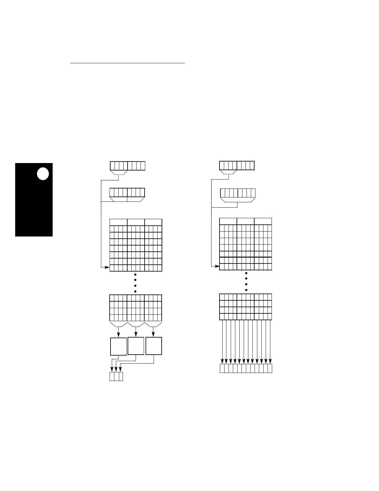
18.3.2.2 COLOR.
Each color pixel is represented as a 4- or 8-bit code in the frame buffer.
Using the color RAM, the pixel code is mapped to a 12-bit red/green/blue (RGB) code, which
allows you to select one of 4,096 colors. For passive color displays, the frame rate control
algorithm processes each color to generate the required amount of intensity, as derived from
the 12 bits (maximum) of RGB information in the color RAM. For active color displays,
12 bits (4 bits per color) are output directly onto the LCD data bus. Figure 18-9 illustrates
color generation. Notice that the LCD data bus is shown with MSB on the left and LSB on
the right. The LCD_A, LCD_B, and LCD_C bits are the least-significant bits of each color,
Figure 18-9. Color Generation
R
GB
011 111 100
COLOR
RAM
ACTIVE DISPLAY
EIGHT BITS PER PIXEL
0110
DISPLAY DATA
FOUR BITS PER PIXEL
0000
0110
10 1 11 1 00 1
0
1
1
1 1
NOTE: * FOR EACH FRAME IN A GROUP OF 16, 1 INDICATES THIS COLOR PIXEL IS ON AND 0 INDICATES THIS COLOR PIXEL IS OFF.
PASSIVE DISPLAY
0110
0000
0110
R
GB
011 111 100
110
DISPLAY DATA
DISPLAY DATA DISPLAY DATA
0
EIGHT BITS PER PIXEL
FOUR BITS PER PIXEL
(256 ENTRIES)
FRC FRC FRC
***
LCD PIXEL
(RED) (GREEN) (BLUE)
LD0
LCD_A
LCD_B
LCD_C
LD8
LD7
LD6
LD5
LD4
LD3
LD2
LD1