Memory Controller
MOTOROLA
MPC823e REFERENCE MANUAL
15-9
MEMORY CONTROLLER
15
15.3.1 Register Descriptions
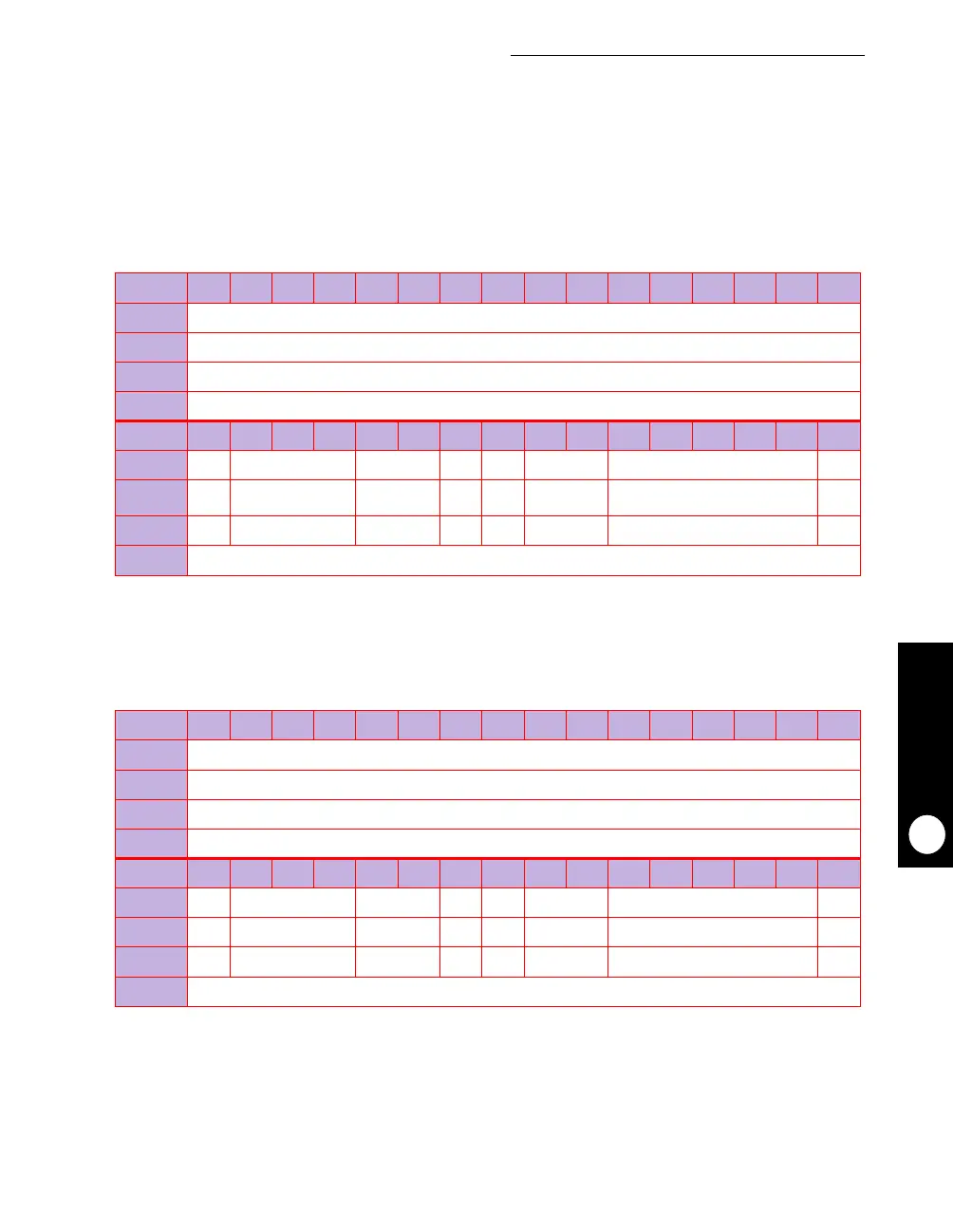
15.3.1.1 BASE REGISTERS.
The base registers (BR0-7) contain the base address and
address types that are used by the memory controller to compare the address bus with the
current address accessed. It also includes a memory attribute and selects the machine for
memory operation handling. After reset, BR0 is referred to as the Boot BR0 and it has a
special functionality until the first write to OR0.
BOOT BR0
BIT
0 1 2 3 4 5 6 7 8 9 10 11 12 13 14 15
FIELD
BA
RESET
0
R/W
R/W
ADDR
(IMMR & 0xFFFF0000) + 0x
100
BIT
16 17 18 19 20 21 22 23 24 25 26 27 28 29 30 31
FIELD
BA AT PS PARE WP MS RESERVED V
RESET
00
*
00 0 0
*
R/W
R/W R/W R/W R/W R/W R/W R/W R/W
ADDR
(IMMR & 0xFFFF0000) + 0x
102
*
This value depends on the value of the hard reset configuration word.
BR
x
BIT
0 1 2 3 4 5 6 7 8 9 10 11 12 13 14 15
FIELD
BA
RESET
0
R/W
R/W
ADDR
(IMMR & 0xFFFF0000) + 0x100 (BR0), 0x
108 (BR1),
0x
110, (BR2),
0x
118 (BR3),
0x
120 (BR4),
0x
128 (BR5),
0x
130 (BR6),
0x
138 (BR7)
BIT
16 17 18 19 20 21 22 23 24 25 26 27 28 29 30 31
FIELD
BA AT PS PARE WP MS RESERVED V
RESET
0 0 0000 0 0
R/W
R/W R/W R/W R/W R/W R/W R/W R/W
ADDR
(IMMR & 0xFFFF0000) + 0x102 (BR0), 0x
10A (BR1),
0x
112, (BR2),
0x
11A (BR3),
0x
122 (BR4),
0x
12A (BR5),
0x
132 (BR6),
0x
13A (BR7)