Instruction Cache
9-6
MPC823e REFERENCE MANUAL
MOTOROLA
INSTRUCTION CACHE
9
CCER1—Instruction Cache Error Type 1
This field is sticky and set by the hardware. It is read-only and cleared when read.
0 = No Error.
1 = Error.
CCER2—Instruction Cache Error Type 2
This field is sticky and set by the hardware. It is read-only and cleared when read.
0 = No Error.
1 = Error.
CCER3—Instruction Cache Error Type 3
This field is sticky and set by the hardware. It is read-only and cleared when read.
0 = No Error.
1 = Error.
Bits 13–31—Reserved
These bits are reserved and must be set to 0.
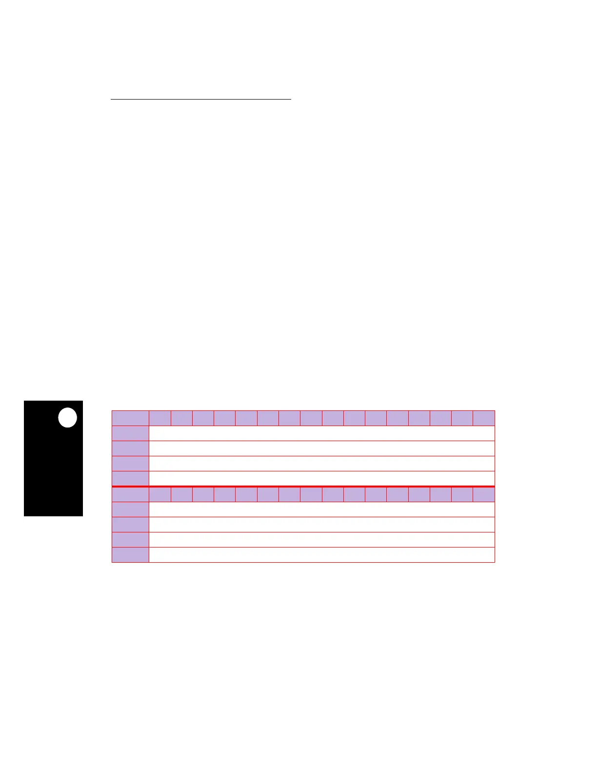
9.2.2 Instruction Cache Address Register
The instruction cache register (IC_ADR) contains addresses to be used in the command
programmed in the IC_CST.
ADR—Address
This field represents the address to be used in the command programmed in the CMD field
of the IC_CST. The format may vary depending on the selected cache operation.
IC_ADR
BIT
0 1 2 3 4 5 6 7 8 9 10 11 12 13 14 15
FIELD
ADR
RESET
—
R/W
R/W
SPR
561
BIT
16 17 18 19 20 21 22 23 24 25 26 27 28 29 30 31
FIELD
ADR
RESET
—
R/W
R/W
SPR
561
NOTE: — = Undefined.