Clocks and Power Control
5-10
MPC823e REFERENCE MANUAL
MOTOROLA
CLOCKS AND POWER
5
CONTROL
5.3 THE CLOCK MODULE
The input frequency source for the phase-locked loop can either be a low frequency crystal
or a high frequency crystal (4MHz) that the phase-locked loop multiplies to produce the
system clock. If you use a low frequency crystal circuitry, the on-chip main clock oscillator
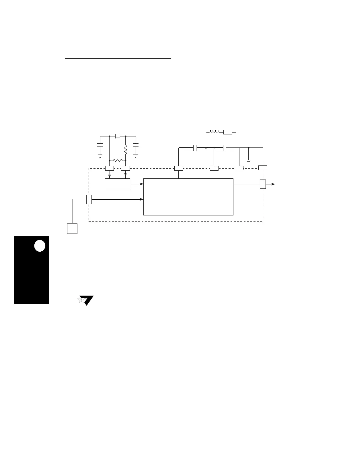
requires an external parallel resonant crystal, two capacitors, and two resistors, as shown
in Figure 5-2. When you design and implement this circuitry, follow normal high-frequency
design rules for placement and layout.
If you use a high-frequency oscillator, its output can be directly input to the EXTCLK pin.
Even though crystals are typically much cheaper, oscillators have more stability because
they are less affected by trace length, component quality, printed circuit board layout and
characteristics.
The MPC823e clock module consists of the main crystal oscillator, the SPLL, the low-power
divider, the clock generator/driver blocks, and the clock module/system low-power control
block. The clock module and system low power control block receive control bits from the
system clock control register (SCCR), PLL low-power and reset control register (PLPRCR),
and reset status register (RSR). Figure 5-3 illustrates the clock module.
Figure 5-2. Crystal Oscillator
Note:
In your design, you must always consider the oscillation startup stablization time
of the crystal. During this stabilization time, no internal or external clocks are
generated by the MPC823e, which may cause higher than normal static current
during the short period of stabilization. Assuming that the crystal circuit is
powered by keep-alive power, then once you system has had first time power-
up, allowance for stabilization is not necessary.
EXTAL
OSCM
XTAL
XFC
VDDSYN
XFC
0.1 F
*
CLKOUT
SPLL
VSSSYN
32 or 38KHz CRYSTAL
A4A5
B2
B1
A1
A2
VSSSYN1
VDD
EXTCLK
3–5MHz
XTAL
OSC
*XFC must be a low-leakage capacitor. See Section 22 Electrical Characteristics for recommended values.
A6
A2
A7
D1
MPC823