Memory Controller
15-4
MPC823e REFERENCE MANUAL
MOTOROLA
MEMORY CONTROLLER
15
15.2 ARCHITECTURE
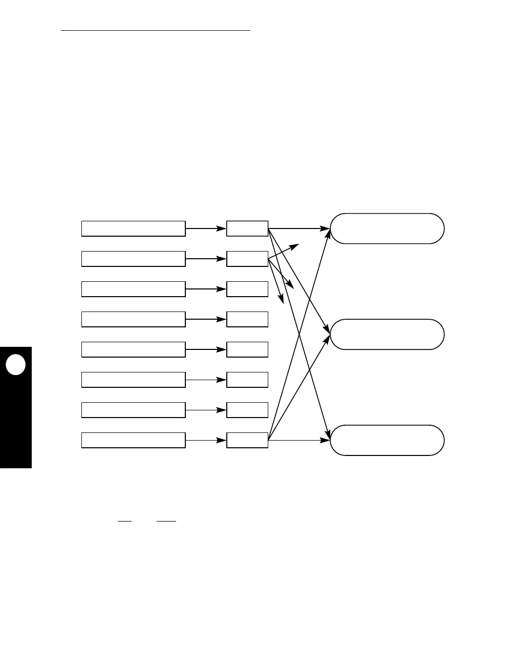
The memory controller consists of three basic machines:
• General-purpose chip-select machine
• User-programmable machine A
• User-programmable machine B
As illustrated in Figure 15-2, each bank can be assigned to any one of these machines via
the MS field in the base register. When a memory address matches the BA field of the base
register, the corresponding machine takes ownership of the external signals that control
access until the cycle terminates.
The general-purpose chip-select machine (GPCM) provides a glueless interface to EPROM,
SRAM, Flash EPROM, and other peripherals. General-purpose chip-select signals are
available on CS
[0:7]. CS0 also functions as the boot chip-select signal that allows the CPU
to access the boot EPROM from reset. Each chip-select allows a maximum of 30 wait states.
Figure 15-2. Memory Controller Machine Selection
USER-PROGRAMMABLE
USER-PROGRAMMABLE
GENERAL-PURPOSE
BANK 0
BANK 1
BANK 2
BANK 3
BANK 4
BANK 5
BANK 6
BANK 7
MS FIELD
MS FIELD
MS FIELD
MS FIELD
MS FIELD
MS FIELD
MS FIELD
MS FIELD
MACHINE A
MACHINE B
MACHINE
CHIP-SELECT