System Interface Unit
MOTOROLA MPC823e REFERENCE MANUAL 12-23
SYSTEM INTERFACE UNIT
12
12.8.1 Periodic Interrupt Status and Control Register
The read/write periodic interrupt status and control register (PISCR) contains the interrupt
request level and the interrupt status bits. It also controls the 16 bits to be loaded in a
modulus counter.
PIRQ—Periodic Interrupt Request Level
This field allows you to configure any interrupt level for periodic interrupts. See Figure 12-2
for interrupt request levels.
PS—Periodic Interrupt Status
This bit can be negated by writing a 1 to it (zero has no effect).
0 = The periodic interrupt timer is unaffected.
1 = The periodic interrupt timer has issued an interrupt.
Bits 9–12—Reserved
These bits are reserved and must be set to 0.
PIE—Periodic Interrupt Enable
0 = Disables the PS bit.
1 = Enables the PS bit to generate an interrupt.
PITF—Periodic Interrupt Timer Freeze Enable
0 = The periodic interrupt timer is unaffected by the FRZ signal.
1 = The FRZ signal stops the periodic interrupt timer.
PTE—Periodic Timer Enable
0 = The periodic interrupt timer is disabled.
1 = The periodic interrupt timer is enabled.
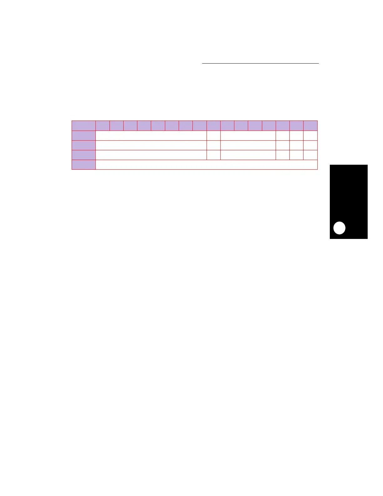
PISCR
BIT 0 1 2 3 4 5 6 7 8 9 10 11 12 13 14 15
FIELD PIRQ PS RESERVED PIE PITF PTE
RESET 0 0 0 001
R/W R/W R/W R/W R/W R/W R/W
ADDR (IMMR & 0xFFFF0000) + 0x240