Development Capabilities and Interface
MOTOROLA MPC823e REFERENCE MANUAL 20-55
DEVELOPMENT
20
CAPABILITIES & INTERFACE
20.6.3 Debug Mode Registers
20.6.3.1 INTERRUPT CAUSE REGISTER. The interrupt cause register (ICR) provides the
reason for entering debug mode. All bits are set by the hardware, cleared when the register
is read, and cleared to zero when exiting reset. Any attempt to write to this register is
ignored. The reset value for this register is 0x00000000.
Bits 0, 4, and 5—Reserved
These bits are reserved and must be set to 0.
RST—Reset Interrupt
This bit is set when the system reset pin is asserted. This pin is not implemented in the core.
CHSTP—Check Stop
This bit is set when the machine check interrupt is asserted and MSR
ME
=0. The core enters
debug mode if enabled and the CHSTPE bit in the DER is set. Otherwise, the processor
enters the check stop state.
MCI—Machine Check Interrupt
This bit is set when the machine check interrupt is asserted and MSR
ME
=1. The core enters
debug mode if enabled and the MCIE bit in the DER is set.
EXTI—External Interrupt
This bit is set when the external interrupt is asserted. The core enters debug mode if enabled
and the EXTIE bit in the DIR is set.
ALI—Alignment Interrupt
This bit is set when the alignment interrupt is asserted. The core enters debug mode if
enabled and the ALIE bit in the DIR is set.
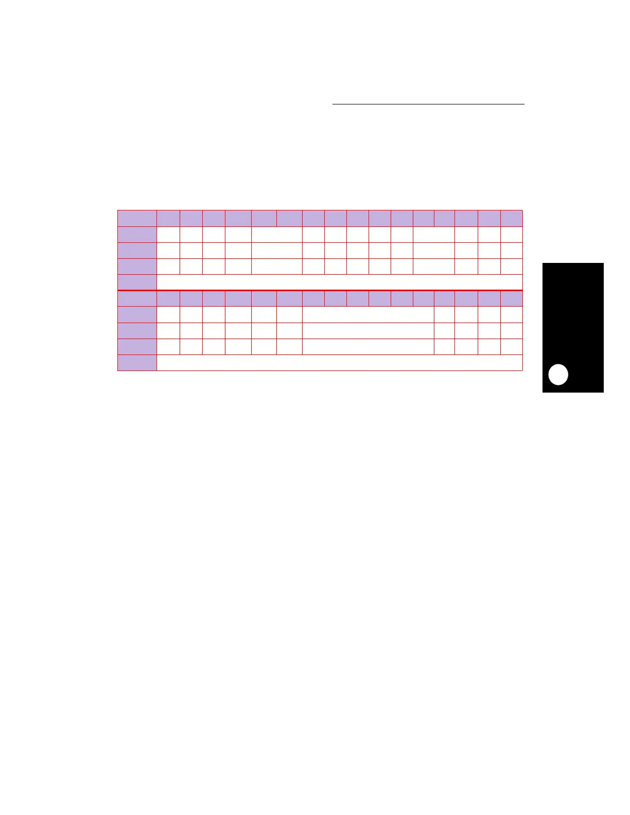
ICR
BIT 0 1 2 3 4 5 6 7 8 9 10 11 12 13 14 15
FIELD
RES RST CHSTP MCI RESERVED EXTI ALI PRI FPUVI DECI RESERVED SYSI TR RES
RESET
000 0 0 00000 0 000
R/W
RRR R R RRRRR R RRR
SPR
148
BIT 16 17 18 19 20 21 22 23 24 25 26 27 28 29 30 31
FIELD
RES SEI ITLBMS DTLBMS ITLBER DTLBER RESERVED LBRK IBRK EBRK DPI
RESET
000 0 0 0 0 0000
R/W
RRR R R R R RRRR
SPR
148