Clocks and Power Control
MOTOROLA
MPC823e REFERENCE MANUAL
5-7
CLOCKS AND POWER
5
CONTROL
5.2.2 PLL, Low-Power, and Reset Control Register
The 32-bit system PLL, low-power, and reset control register (PLPRCR) is powered by a
keep-alive power supply and is used to control the system frequency and low-power mode
operation.
MF—Multiplication Factor
The output of the voltage control oscillator (VCO) frequency is divided to generate the
feedback signal that goes to the phase comparator. This field controls the value of the
divider in the SPLL feedback loop. The phase comparator determines the phase shift
between the feedback signal and the reference clock. This difference results in an increase
or decrease of the VCO output frequency.
The MF field can be read and written at any time. Changing the MF field causes the SPLL
to lose its lock. All clocks are disabled until the SPLL reaches lock condition. The normal
reset value for the DFNH bits is 0x0 (divide-by-one). When the SPLL is operating in
one-to-one mode, the MF field is set to 0. See Table 5-2 for details.
Bits 12–15—Reserved
These bits are reserved and must be set to 0.
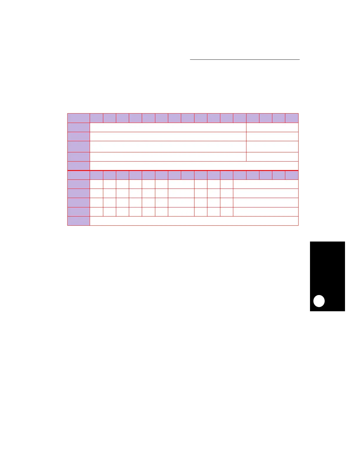
PLPRCR
BIT
0 1 2 3 4 5 6 7 8 9 10 11 12 13 14 15
FIELD
MF RESERVED
HRESET
— 0
POR
*
0
R/W
R/W RW
ADDR
(IMMR & 0xFFFF0000) + 0x284
BIT
16 17 18 19 20 21 22 23 24 25 26 27 28 29 30 31
FIELD
SPLSS TEXPS RES TMIST RES CSRC LPM CSR LOLRE FIOPD RESERVED
HRESET
—10000 0 ——— 0
POR
010000 0 000 0
R/W
R/W R/W R/W R/W R/W R/W R/W R/W R/W R/W R/W
ADDR
(IMMR & 0xFFFF0000) + 0x286
NOTE: HRESET is hard reset and POR is power-on reset.
— = Undefined.
*
Depends on the combination of MODCK1and MODCK2. See Table 5-2 for more information.