The PowerPC Core
6-20 MPC823e REFERENCE MANUAL MOTOROLA
CORE
6
6.4.1.2 POWERPC STANDARD CONTROL REGISTER BIT ASSIGNMENT
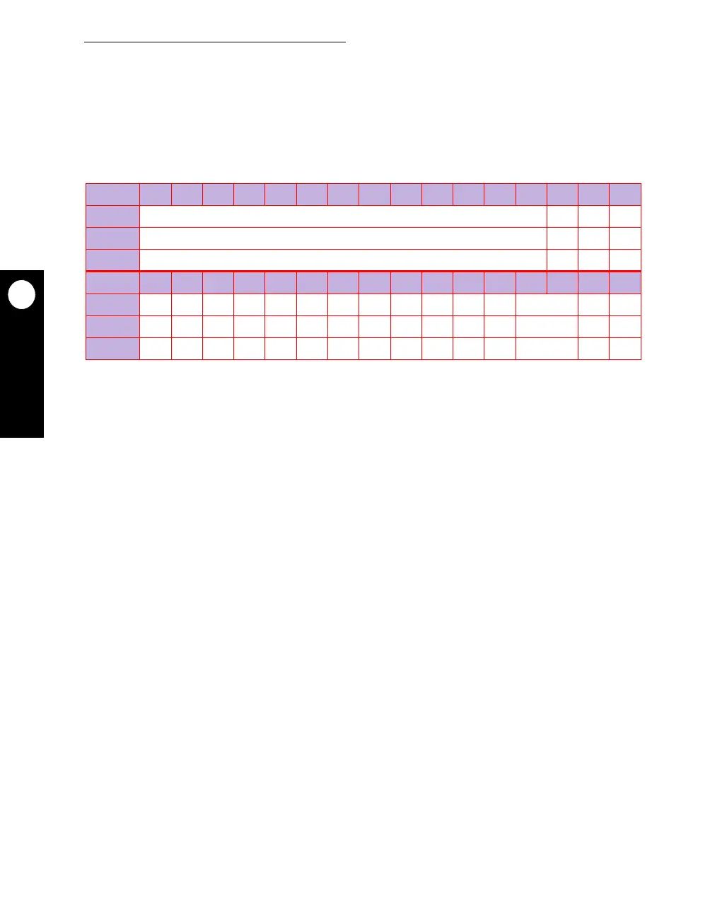
6.4.1.2.1 Machine State Register. The 32-bit machine state register (MSR) defines the
state of the processor. It can be read by the mfmsr instruction. However, it can be modified
by the mtmsr, sc, and rfi instructions, as well as the hard reset configuration word. Refer to
Section 4.3.1.1 Hard Reset Configuration Word for more information.
Bits 0–12—Reserved
These bits are reserved and must be set to 0. Bits 0, 5, and 9 are loaded from the
corresponding bit in the MSR when an interrupt is taken. The appropriate bit in the MSR is
loaded from this bit when an rfi is executed. Reserved bits in the MSR are set from the
source value on write and return the value last set for it on read.
POW—Power Management Enable
When this bit is set, it allows you to automatically switch between low and high frequency
operation or between normal low mode and normal high mode. When this bit is cleared,
power management is disabled. Refer to Section 5 Clocks and Power Control for more
information on bus power management.
Bit 14—Reserved
This bit is reserved and must be set to 0.
ILE—Interrupt Little-Endian Mode
When an exception occurs, this bit is copied into the MSR to select the endian mode for the
context established by the exception.
0 = Big-endian mode is selected.
1 = Little-endian mode is selected.
EE—External Interrupt Enable
This bit is loaded from the corresponding bit in the MSR when an interrupt is taken. The
appropriate bit in the MSR is loaded from this bit when an rfi is executed.
MSR
BIT 0 1 2 3 4 5 6 7 8 9 10 11 12 13 14 15
FIELD RESERVED POW RES ILE
RESET 0 000
R/W R/W R/W R/W R/W
BIT 16 17 18 19 20 21 22 23 24 25 26 27 28 29 30 31
FIELD EE PR FP ME FE0 SE BE FE1 RES IP IR DR RESERVED RI LE
RESET 000000000—00 — 00
R/W R/W R/W R/W R/W R/W R/W R/W R/W R/W R/W R/W R/W R/W R/W R/W
NOTE: — = Undefined.