LCD Controller
MOTOROLA
MPC823e REFERENCE MANUAL
18-15
LCD CONTROLLER
18
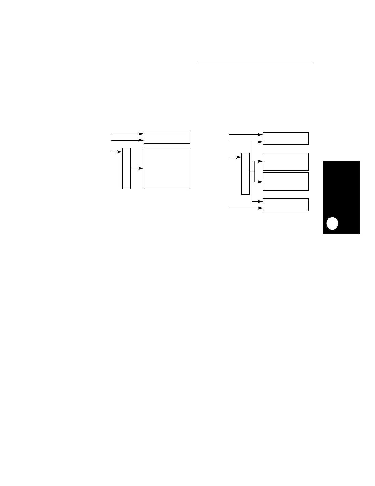
18.3.9.1 SINGLE-SCAN AND DUAL-SCAN PANELS.
Some LCD panels split the display
area into two horizontal halves that are scanned at the same time so that two lines are
shifted and displayed simultaneously in each half. In this case, half of the data bus is used
to drive the upper half of the screen and the other half is used to drive the lower half.
Figure 18-10 illustrates single-scan and dual-scan LCD panels.
18.3.9.2 PASSIVE INTERFACE.
Passive LCD interfaces use the following signals. These
signals have a programmable polarity. T
cyc
is the cycle time of the LCD clock (SHIFT/CLK).
T
delay
is a circuit delay.
• SHIFT/CLK—On the asserted edge of SHIFT, data is latched into the X shift register.
• FRAME/VSYNC—The FRAME signal initiates the frame by putting the Y pointer at the
first row.
• LOAD/HSYNC—The LOAD signal transfers the contents of the shift register into the
drive latches.
• LCD_AC/LOE—The LCD alternating current signal toggles every few frames to nullify
any DC voltage. The toggle rate is programmable.
• LD—The width of this data bus is configured to 4 or 8 bits.
A general-purpose I/O can be used to output an integrated signal or pulse-width modulation
(PWM) waveform and its duty cycle controls the RMS value of the voltage to the panel. The
PWM signal is generated by one of the communication processor module timers. Refer to
Section 16.2.6 RISC Microcontroller Commands
for more details.
Figure 18-10. Single-Scan and Dual-Scan LCD Panels
DATA (4 OR 8 BITS)
SHIFT, LOAD
FRAME, LOAD
ARRAY
X BY Y PIXELS
X
Y
DATA (2 OR 4 BITS)
SHIFT, LOAD
FRAME, LOAD
0
Y
ARRAY
0 BY Y / 2 PIXELS
ARRAY
X BY Y / 2 PIXELS
X
DATA (2 / 4 BITS)
DUAL-SCAN DISPLAY
SINGLE-SCAN DISPLAY
 Loading...

