LCD Controller
18-30 MPC823e REFERENCE MANUAL MOTOROLA
LCD CONTROLLER
18
18.4.7 Color RAM Operation Modes
The color RAM contains 256 entries that are each 16 bits wide. It is located in the dual-port
RAM and is not initialized at reset. Your LCD panel and its required mode will dictate how
the display or system memory and the color RAM is configured.
18.4.7.1 ONE BIT PER PIXEL MONOCHROME MODE. When you are using this mode
(TFT=0, BPIX=00, and CLOR=0), configure color RAM using the following pattern. You
must program the first 16 entries of the color RAM to be transparent.
Bits 0–11—Reserved
These bits are reserved and must be set to 0.
Note: Before programming the color RAM, you must program the LCCR to the specific
data coding, number of bits per pixel, color or monochrome, etc.
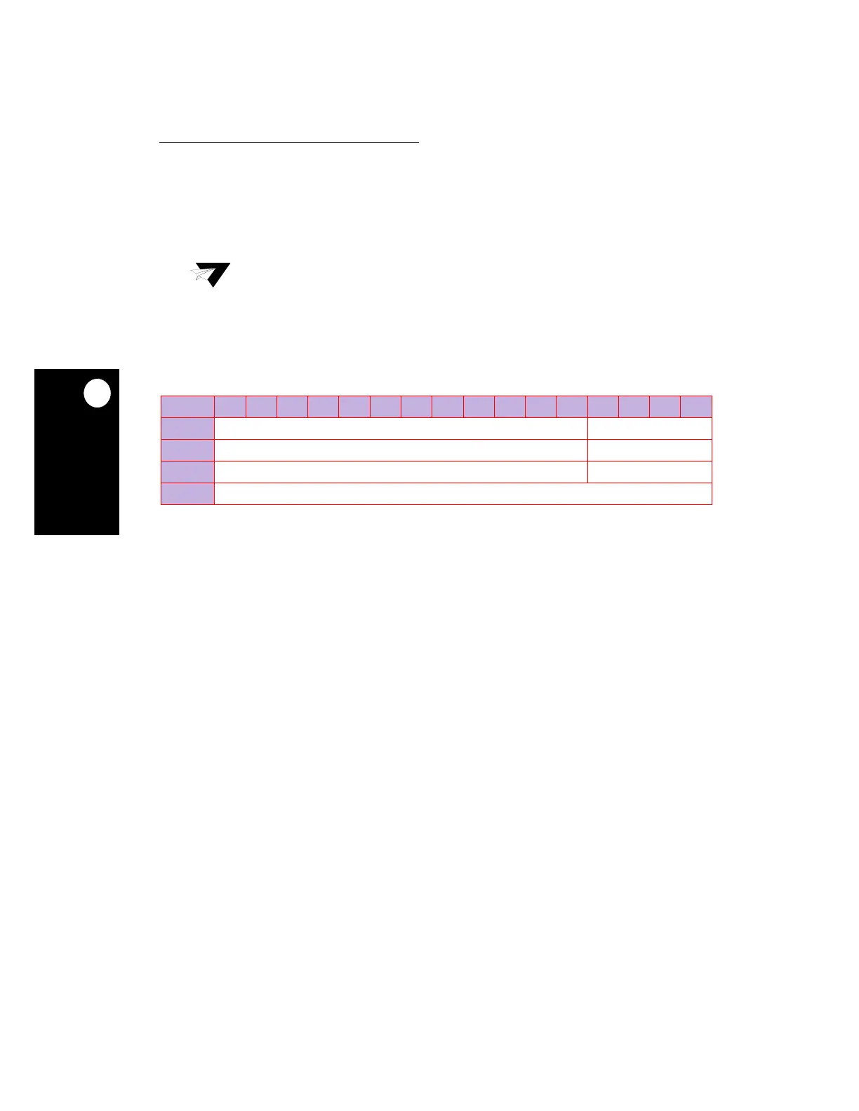
BIT 0 1 2 3 4 5 6 7 8 9 10 11 12 13 14 15
FIELD RESERVED GLC
RESET ——
R/W R/W R/W
ADDR (IMMR & 0xFFFF0000) + (DPR) 0xE00—0xE1F
NOTE: — = Undefined.
 Loading...

