LCD Controller
18-32 MPC823e REFERENCE MANUAL MOTOROLA
LCD CONTROLLER
18
18.4.7.2 TWO BITS PER PIXEL GRAYSCALE MODE. In 2-bits per pixel grayscale mode,
the LCD controller provides four possible shades to be loaded into each pixel of the LCD
panel. The two bits of data are provided by each display memory word that is accessed by
the DMA controller. This value will then index into the color RAM at addresses 1, 3, 5, and
7. You can provide any four of 16 possible shades by loading the color RAM addresses
shown below.
Bits 0–7—Reserved
These bits are reserved and must be set to 0.
GLCA/GLCB—Grayscale Level Code A and B
This field is a 4-bit code that represents the grayscale level for a given pixel code. GLCA and
GLCB must be programmed to the same value. The 4-bit code must be programmed in one
of the following ways:
• Program address 1 of the color RAM with the grayscale level code that corresponds to
pixel code 00 that was retrieved from display memory.
• Program address 3 of the color RAM with the grayscale level code that corresponds to
pixel code 01 that was retrieved from display memory.
• Program address 5 of the color RAM with the grayscale level code that corresponds to
pixel code 10 that was retrieved from display memory.
• Program address 7 of the color RAM with the grayscale level code that corresponds to
pixel code 11 that was retrieved from display memory.
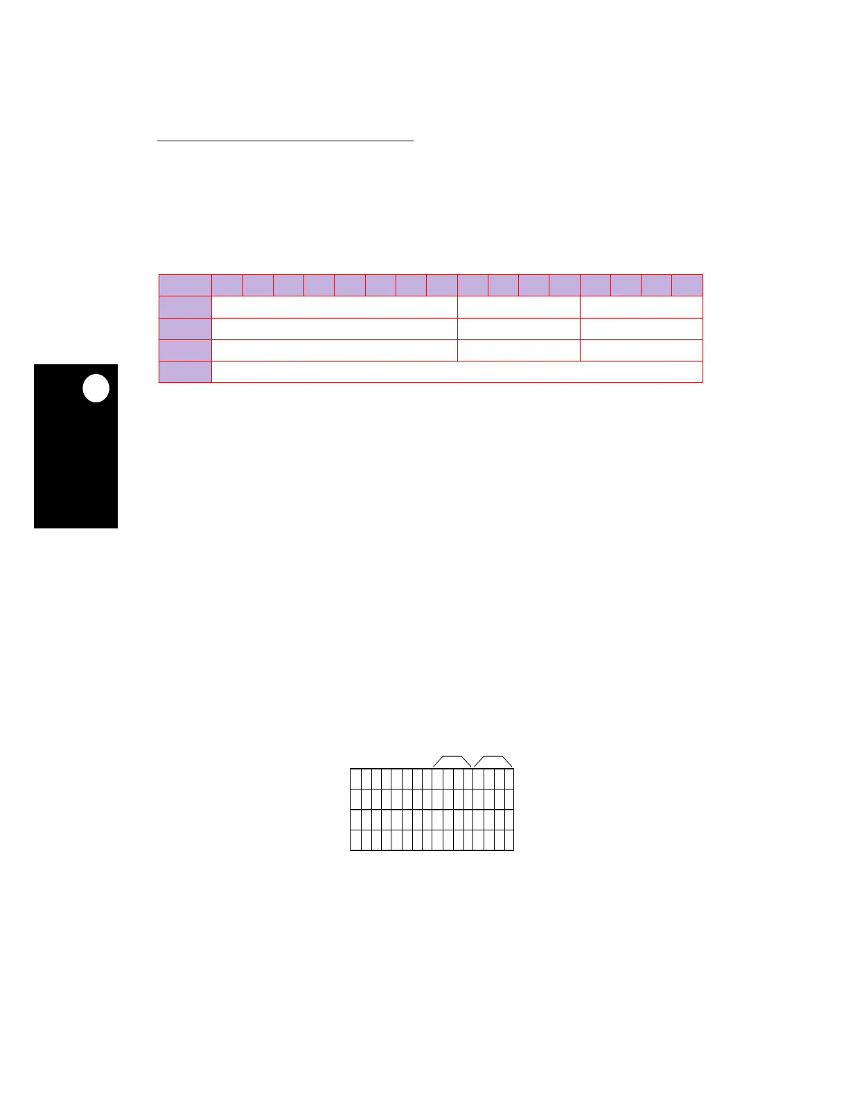
BIT 0 1 2 3 4 5 6 7 8 9 10 11 12 13 14 15
FIELD RESERVED GLCB GLCA
RESET ———
R/W R/W R/W R/W
ADDR (IMMR & 0xFFFF0000) + (DPR) 0xE00—0xE07
NOTE: — = Undefined.
Figure 18-14. Color RAM Entries for Two Bits Per Pixel Mode
1
3
5
7
GLCB GLCA
00000000
00000000
00000000
00000000
0
2
4
6
 Loading...

