Development Capabilities and Interface
MOTOROLA MPC823e REFERENCE MANUAL 20-17
DEVELOPMENT
20
CAPABILITIES & INTERFACE
20.3.2.2 LOAD/STORE SUPPORT. There are two load/store address comparators (E and
F) that compare the 32 address bits and the cycle’s attributes (read/write). The two
least-significant bits are masked ignored when a word is accessed and the least-significant
bit is masked when a half-word is accessed. Each comparator generates two output
signals—equal to and less than. These signals generate one of four events from each
comparator—equal to, not equal to, greater than, or less than. For more information, refer
to Section 20.3.1.2 Byte And Half-Word Working Modes.
There are two load/store data comparators (G and H) that are 32 bits wide and can be
programmed to treat numbers as signed or unsigned values. Each data comparator
operates as four independent byte comparators that have a mask bit and generate two
output signals—equal to and less than (if the mask bit is not set.) Therefore, each 32-bit
comparator has eight output signals that generate the “equal to and less than” signals
according to the compare size that you program (byte, half-word, word). When operating in
byte mode, all signals are significant. In half-word mode only four signals from each
comparator are significant and in word mode only two signals are significant.
One of the following four match events are generated by the equal to and less than
signals—equal to, not equal to, greater than, or less than—depending on the programmed
compare type. Therefore, from the two 32-bit comparators, eight match indications are
generated—Gmatch[0:3] and Hmatch[0:3]. According to the lower bits of the address and
the size of the cycle, only match indications detected on bytes with valid information are
validated. The rest are negated. If the executed cycle has a smaller size than the compare
size (a byte access when the compare size is word or half-word), no match indication will be
asserted. Using the match indication signals, four load/store data events are generated as
shown in Table 20-5.
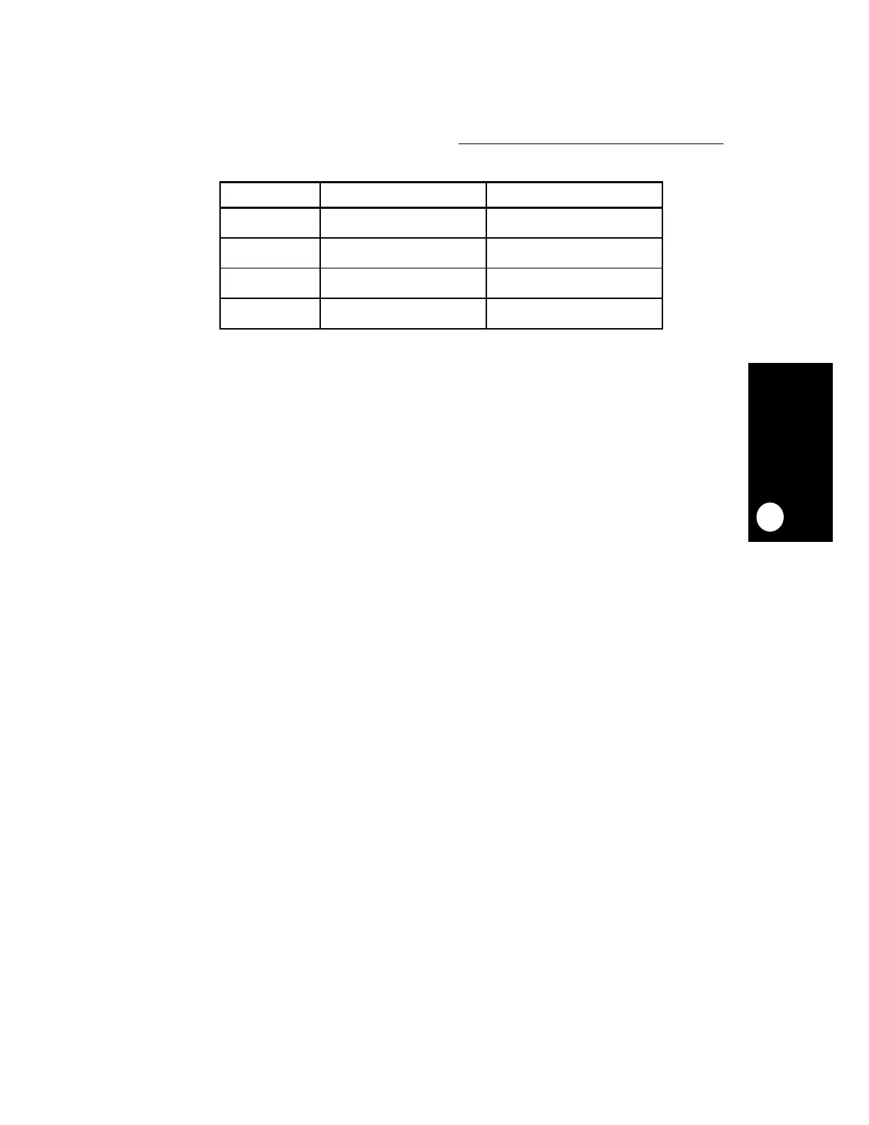
Table 20-4. Instruction Watchpoints Programming Options
NAME DESCRIPTION PROGRAMMING OPTIONS
IW0 First instruction watchpoint Comparator A
Comparators (A & B)
IW1 Second instruction watchpoint Comparator B
Comparator (A | B)
IW2 Third instruction watchpoint Comparator C
Comparators (C & D)
IW3 Fourth instruction watchpoint Comparator D
Comparator (C | D)
 Loading...

