Development Capabilities and Interface
MOTOROLA MPC823e REFERENCE MANUAL 20-27
DEVELOPMENT
20
CAPABILITIES & INTERFACE
• Peripheral breakpoint from the development port generated by external modules are
recognized only when MSR
RI
=1.
• Development port nonmaskable interrupt occurs as a result of a debug station request.
Useful in some catastrophic events, such as an endless loop when MSR
RI
=0. As a
result of this event, the machine can enter a nonrestartable state.
The processor enters into the debug mode state when at least one of the bits in the ICR is
set, the corresponding bit in the DER is enabled, and debug mode is enabled. When debug
mode is enabled and an enabled event occurs, the processor waits until its pipeline is empty
and then starts fetching the next instructions from the development port. For information on
the exact value of the SRR0 and SRR1 registers, refer to Section 7.3.7.3 Definitions.
When the processor is in debug mode, the freeze indication is asserted, thus allowing any
properly programmed peripheral to stop. The fact that the core is in debug mode is also
broadcasted to the external world using the value b’11’ on the VFLS pins. The freeze signal
can be asserted by the software when debug mode is disabled. The development port must
read the value of the ICR to discover the cause of debug mode entry. Reading the ICR clears
all of its bits.
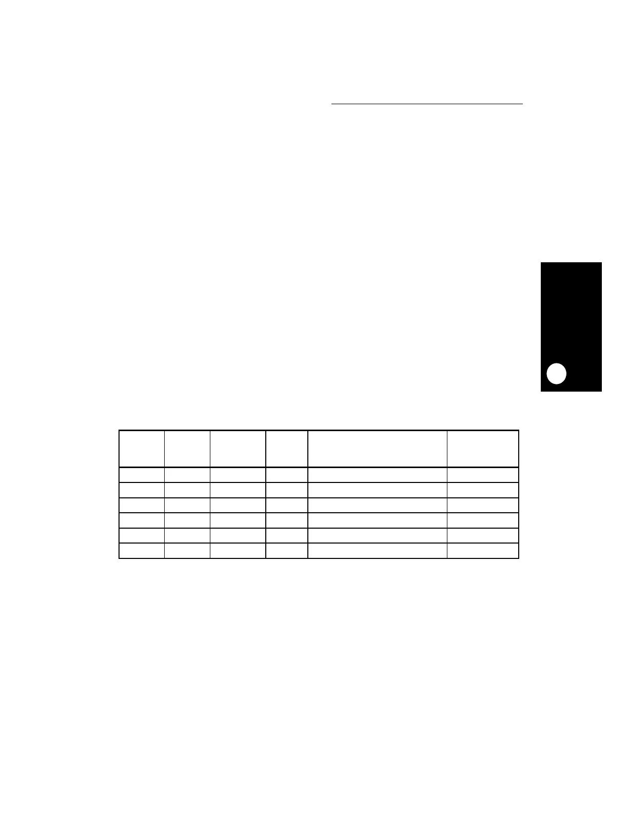
20.4.2.3 CHECKSTOP STATE AND DEBUG MODE. The core enters checkstop state if
the machine check interrupt is disabled (MSR
ME
=0) and a machine check interrupt is
detected. However, if a machine check interrupt is detected when MSR
ME
=0, debug mode
is enabled, the checkstop enable bit in the DER is set, and the core enters debug mode
rather than the checkstop state. The various actions taken by the core when a machine
check interrupt is detected are provided in the following table.
Table 20-7. Checkstop State and Debug Mode
DEBUG
MODE
ENABLE
MSR
ME
CHSTPE
1
MCIE
2
ACTION PERFORMED BY THE CORE
WHEN A MACHINE
CHECK INTERRUPT IS DETECTED
ICR
VALUE
0 0 X X Enter Checkstop State 0x20000000
0 1 X X Branch to the Machine Check Interrupt 0x10000000
1 0 0 X Enter Checkstop State 0x20000000
1 0 1 X Enter Debug Mode 0x20000000
1 1 X 0 Branch to the Machine Check Interrupt 0x10000000
1 1 X 1 Enter Debug Mode 0x10000000
NOTES:
1. The checkstop enable bit of the DER register.
2. The machine check interrupt enable bit of the DER register.
 Loading...

