IEEE 1149.1 Test Access Port
21-4
MPC823e REFERENCE MANUAL
MOTOROLA
IEEE 1149.1 TEST
21
ACCESS PORT
21.2 THE BOUNDARY SCAN REGISTER
The MPC823e scan chain implementation has a 397-bit boundary scan register that
contains bits for all device signal, clock pins, and associated control signals. However, the
XTAL, EXTAL, and XFC pins are associated with analog signals and are not included in the
boundary scan register. An IEEE-1149.1-compliant boundary scan register has been
included on the MPC823e. This 397-bit boundary scan register can be connected between
the TDI and TDO signals when the
extest
or
sample
/
preload
instructions are selected. It is
used for capturing signal pin data on the input pins, forcing fixed values on the output signal
pins, and selecting the direction and drive characteristics (a logic value or high impedance)
of the bidirectional and three-state signal pins. Figure 21-3 through Figure 21-6 depict the
various cell types.
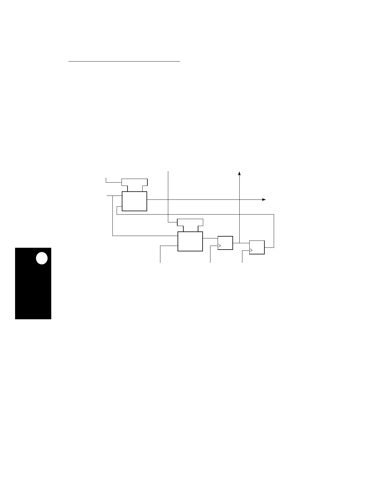
Figure 21-3. Output Pin Cell (O.Pin)
1
1
MUX
G1
1
1
MUX
G1
C
D
C
D
FROM LAST CELL
CLOCK DR
UPDATE DR
SHIFT DR
1 —
EXTEST | CLAMP
DATA FROM
TO OUTPUT
BUFFER
0 —
OTHERWISE
LOGIC
SYSTEM
TO NEXT CELL
 Loading...

