External Bus Interface
13-26 MPC823e REFERENCE MANUAL MOTOROLA
EXTERNAL BUS
13
INTERFACE
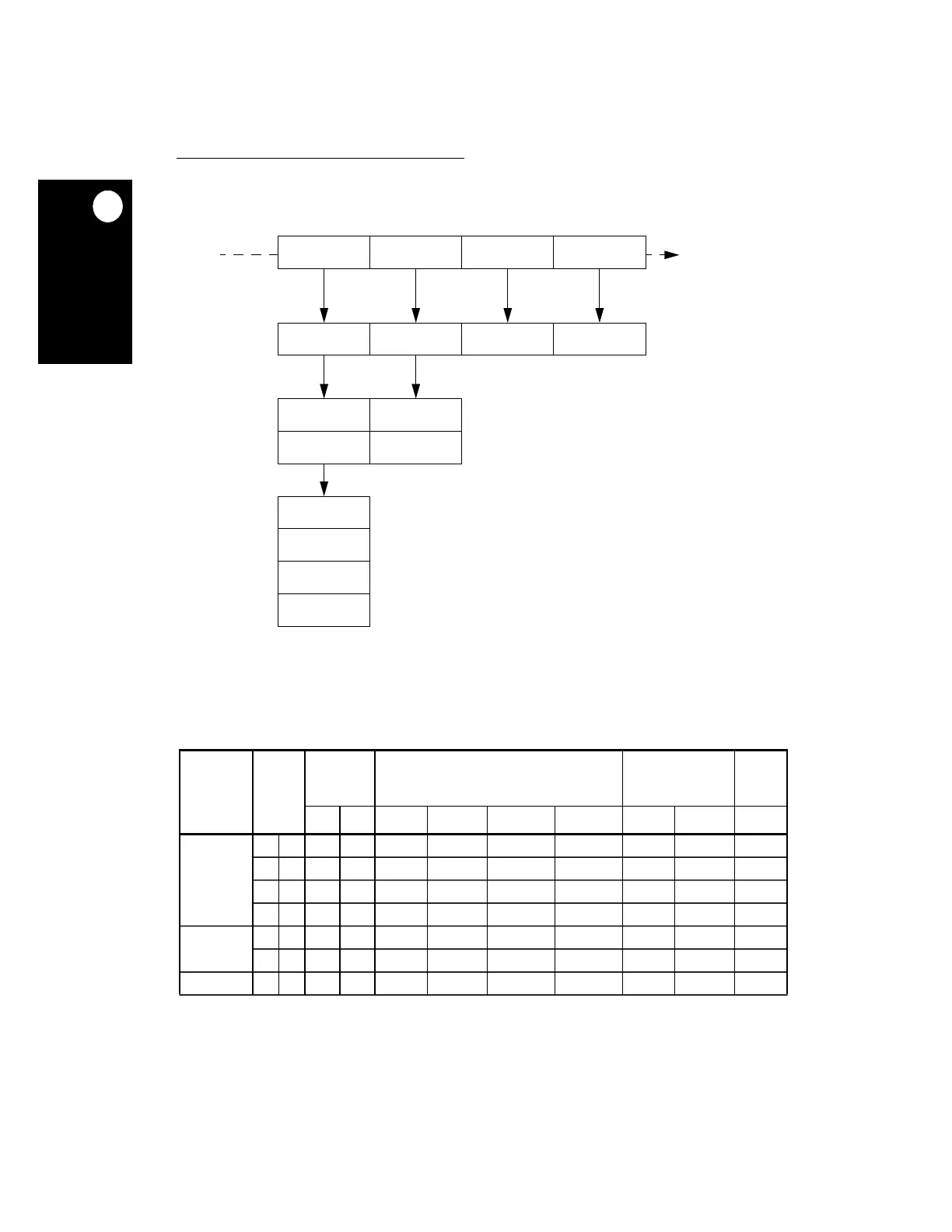
Figure 13-19 illustrates the device connections on the data bus.
Table 13-2 lists the bytes for read cycles required on the data bus.
Figure 13-19. Interface To Different Port Size Devices
Table 13-2. Data Bus Requirements For Read Cycles
TRANSFER
SIZE
TSIZE
[0:1]
INTERNAL
ADDRESS
32-BIT PORT SIZE 16-BIT PORT SIZE 8-BIT
PORT
SIZE
A30 A31 D0–D7 D8–D15 D16–D23 D24–D31 D0–D7 D8–D15 D0–D7
Byte 0 1 0 0 OP0 — — — OP0 — OP0
0 1 0 1 — OP1 — — — OP1 OP1
0 1 1 0 — — OP2 — OP2 — OP2
0 1 1 1 — — — OP3 — OP3 OP3
Half-Word 1 0 0 0 OP0 OP1 — — OP0 OP1 OP0
1 0 1 0 — — OP2 OP3 OP2 OP3 OP2
Word 0 0 0 0 OP0 OP1 OP2 OP3 OP0 OP1 OP0
NOTE: — Denotes that a byte is not required during that read cycle.
32-BIT PORT SIZE
OP0
OP1
OP2
OP3
OP0 OP1 OP2 OP3
OP0 OP1
OP2 OP3
OP0 OP1 OP2 OP3
16-BIT PORT SIZE
8-BIT PORT SIZE
D[0:7] D[8:15] D[16:23] D[24:31]
INTERFACE
OUTPUT
REGISTER