Communication Processor Module
MOTOROLA MPC823e REFERENCE MANUAL 16-19
RISC
COMMUNICATION
16
PROCESSOR MODULE
• TM_BASE—This index pointer contains a 16-bit offset from the beginning of the
dual-port RAM to the location of your timer table entry. For the timer table entry area,
you must allocate four bytes for each timer used. If you use all 16 timers, you must
allocate 64 bytes in the timer table entry area. If you do not use all the timers, the timers
must always be allocated in ascending order to save space. For example, if you only
need two timers, then 8 bytes are required for the timer table entry area as long as you
only enable RISC timers 0 and 1.
• TM_PTR—This index pointer is used exclusively by the RISC microcontroller to point
to the next entry to be executed in the timer table. You must not modify this pointer.
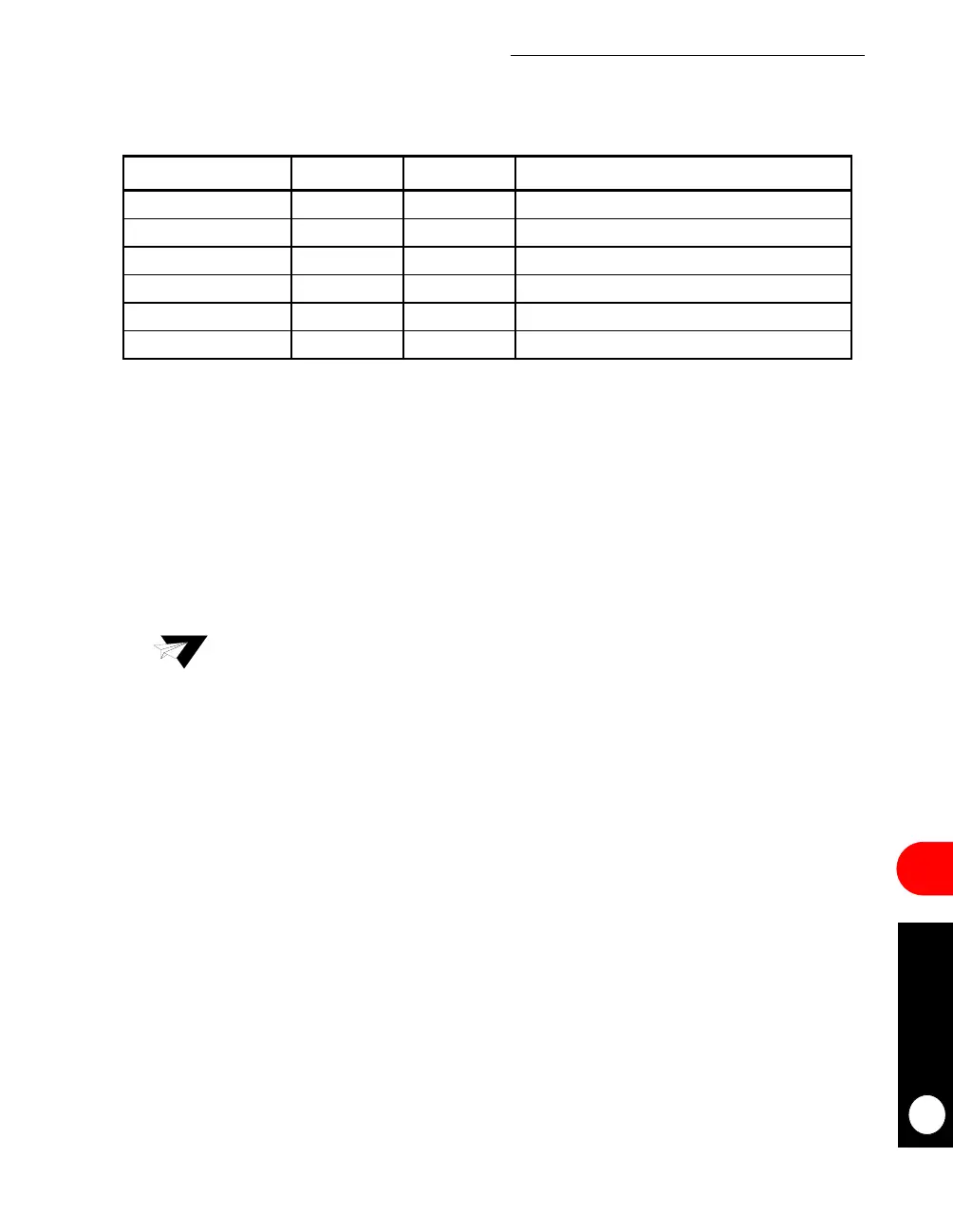
Table 16-4. RISC Timer Table Parameter RAM Memory Map
ADDRESS NAME WIDTH DESCRIPTION
Timer Base + 00 TM_BASE Half-word RISC Timer Table Base Address Index Pointer
Timer Base + 02 TM_PTR Half-word RISC Timer Table Pointer
Timer Base + 04 R_TMR Half-word RISC Timer Mode Register
Timer Base + 06 R_TMV Half-word RISC Timer Valid Register
Timer Base + 08 TM_CMD Word RISC Timer Command Register
Timer Base + 0C TM_CNT Word RISC Timer Internal Counter
NOTE: You are only responsible for initializing the items in bold.
Timer Base = (IMMR & 0xFFFF0000) + 0x3DB0.
Note: The timer table entry area pointed to by the TM_BASE must always be aligned
to a word boundary that is evenly divisible by four.
 Loading...

