Communication Processor Module
MOTOROLA MPC823e REFERENCE MANUAL 16-21
RISC
COMMUNICATION
16
PROCESSOR MODULE
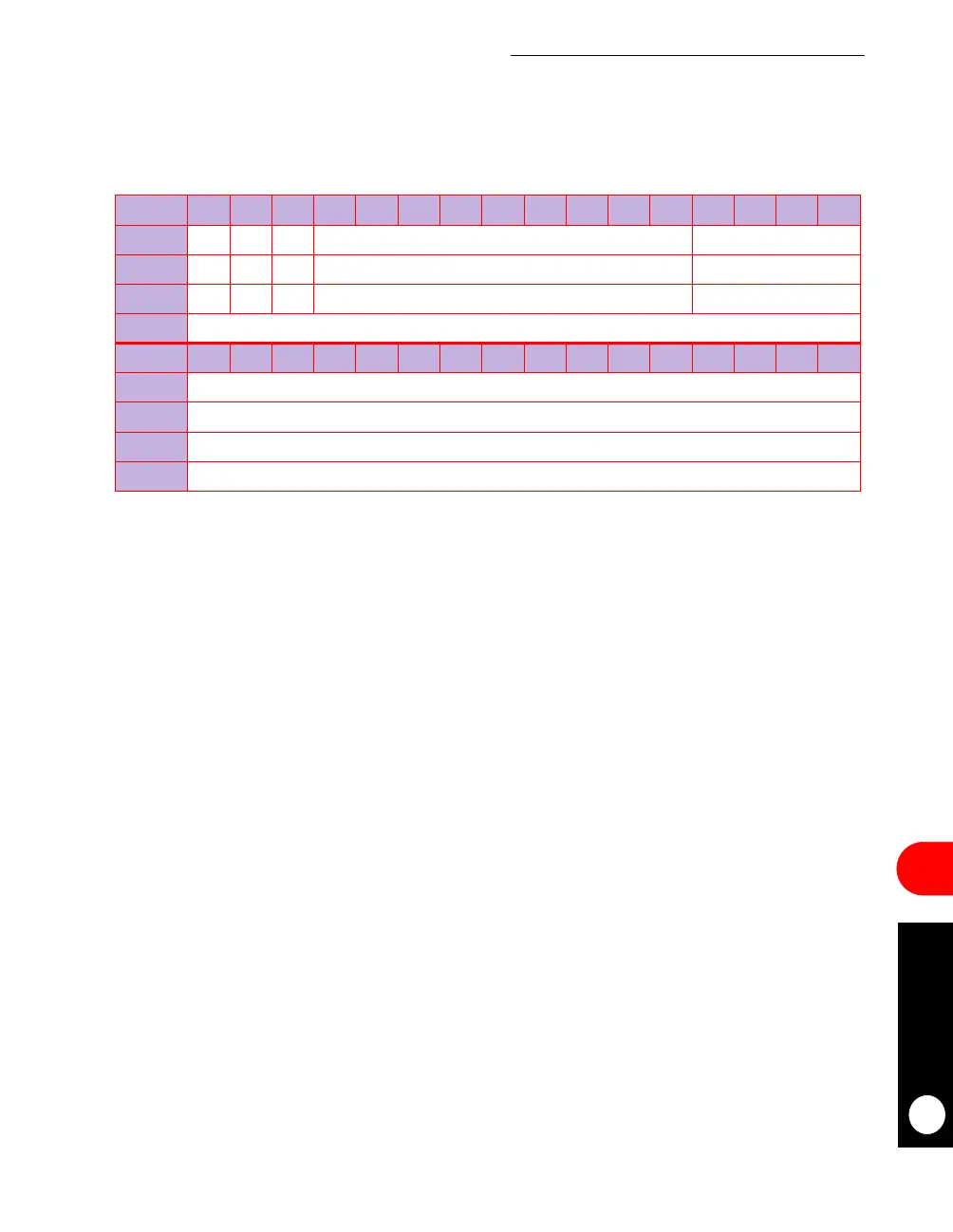
• TM_CMD—This register is used as a parameter location when the SET TIMER
command is issued. You must write this location prior to issuing the SET TIMER
command. The bits of this register are defined as follows.
V—Valid
0 = Disables the timer.
1 = Enables the timer.
R—Restart
0 = One-shot timer operation.
1 = Automatic timer restart.
PWM—Pulse-Width Modulation Mode
0 = Normal mode.
1 = Pulse-width modulation.
Bits 3–11—Reserved
These bits are reserved and must be set to 0.
TIMER NUMBER
This bit is the value from zero to 15 that signifies timer configuration.
TIMER PERIOD
This bit is the 16-bit timeout value of the timer. The maximum value is 65,536 and is
encoded as 0x0000.
• TM_CNT—This register is a tick counter that the microcontroller updates after each tick
or after the timer table is scanned. It is updated if the microcontroller’s internal timer is
enabled, regardless of whether any of the 16 timers are enabled, and it can be used to
track the number of ticks the microcontroller receives and responds to.
TM_CMD
BIT 0 1 2 3 4 5 6 7 8 9 10 11 12 13 14 15
FIELD V R PWM RESERVED TIMER NUMBER
RESET 000 0 0
R/W R/W R/W R/W R/W R/W
ADDR (IMMR & 0xFFFF0000) + 0x3DB8
BIT 16 17 18 19 20 21 22 23 24 25 26 27 28 29 30 31
FIELD TIMER PERIOD
RESET 0
R/W R/W
ADDR (IMMR & 0xFFFF0000) + 0x3DBA
 Loading...

