Communication Processor Module
MOTOROLA MPC823e REFERENCE MANUAL 16-29
DSP
COMMUNICATION
16
PROCESSOR MODULE
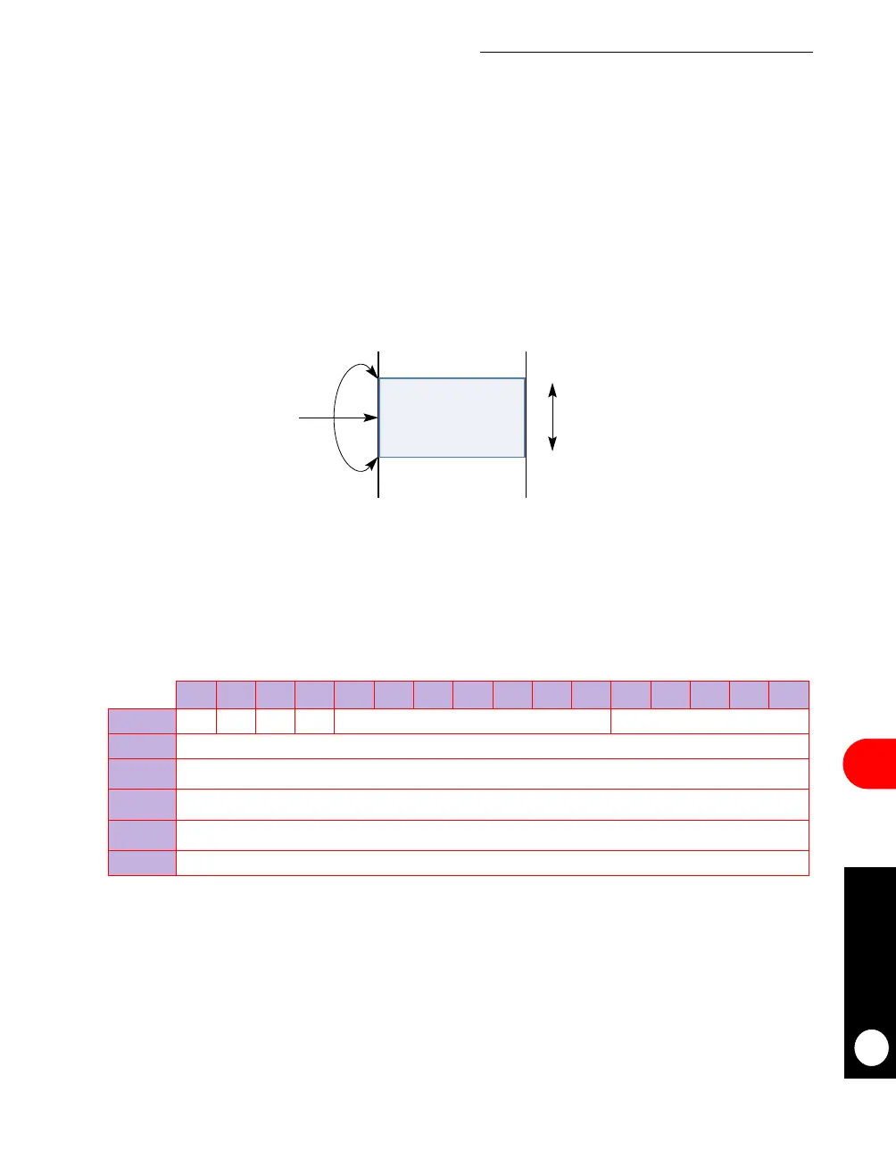
16.3.3.2 MODULO ADDRESSING. The input and output buffers are circular within a
certain programmable size that must be a multiple of 2
k
. The base address of the circular
buffer must be aligned on its natural size boundary. For example, if your input buffer size is
128 bytes, your base address must be aligned on a 128-byte boundary. In other words, the
lower boundary (base address) of a circular buffer containing modulus (M) bytes must have
zeros in the k LSBs of the base address, where 2
k
≥ M, and therefore must be a multiple of
2
k
. The upper boundary is the lower boundary, plus the size minus one (base address +
M-1). Once M is chosen, a sequential series of memory blocks (each of length 2
k
) is created
where these circular buffer can be located. If M < 2
k
, there is a 2
k
-M space between the
sequential M-sized circular buffers and M must be a multiple of four. See Figure 16-9 for
details.
16.3.3.2.1 DSP Function Descriptors. Each function descriptor is composed of eight
16-bit half-words. The first half-word contains the function opcode as well as status and
control bits and the other half-words contain the function’s parameter packet. Each function
has its own parameter packet.
S—STOP
0 = Do not stop after executing this function descriptor.
1 = Stop after executing this function descriptor.
Bits 1 and 4–10—Reserved
These bits are reserved and must be set to 0.
Figure 16-9. Circular Buffer
0 1 2 3 4 5 6 7 8 9 10 11 12 13 14 15
OFFSET + 0 S RES W I RESERVED OPCODE
OFFSET + 2 PARAMETER 1
• • •
• • •
• • •
• • •
• • •
• • •
OFFSET + E PARAMETER 7
UPPER BOUNDARY
LOWER BOUNDARY
M = MODULUSADDRESS
POINTER
CIRCULAR
BUFFER
 Loading...

