Communication Processor Module
MOTOROLA MPC823e REFERENCE MANUAL 16-37
DSP
COMMUNICATION
16
PROCESSOR MODULE
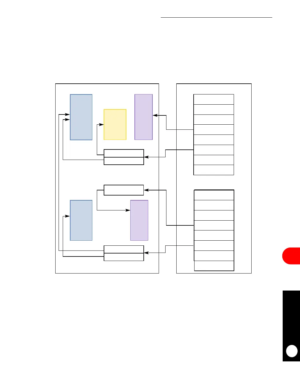
16.3.3.5.2 DSP Programming Example (Core and CPM). Figure 16-11 illustrates the
organization of the data buffer and function descriptor data in system memory and dual-port
RAM. The function descriptor resides in system memory and all input, ouput, and coefficient
data must reside in dual-port RAM. The transmit and modulation function descriptor chain
can reside in either system memory or dual-port RAM.
Figure 16-11. Core and CPM Implementation
INPUT POINTER
OUTPUT POINTER
OPCODE = FIR2
TX FILTER FD
# OF ITTERATIONS
# OF TAPS
COEFF BASE
IN BUFFER SIZE
XYPTR
INPUT
BUFFER
OUTPUT
BUFFER
COEFF
TABLE
OPCODE = MOD
MODULATION FD
# OF ITTERATIONS
MOD TABLE SIZE
MPTR
IN BUFFER SIZE
XYPTR
INPUT POINTER
OUTPUT
BUFFER
MOD
TABLE
MOD TABLE PTR
SYSTEM MEMORYDUAL-PORT RAM
OUT BUFFER SIZE
OUT BUFFER SIZE
OUTPUT POINTER



 To Next Page