Communication Processor Module
MOTOROLA MPC823e REFERENCE MANUAL 16-39
DSP
COMMUNICATION
16
PROCESSOR MODULE
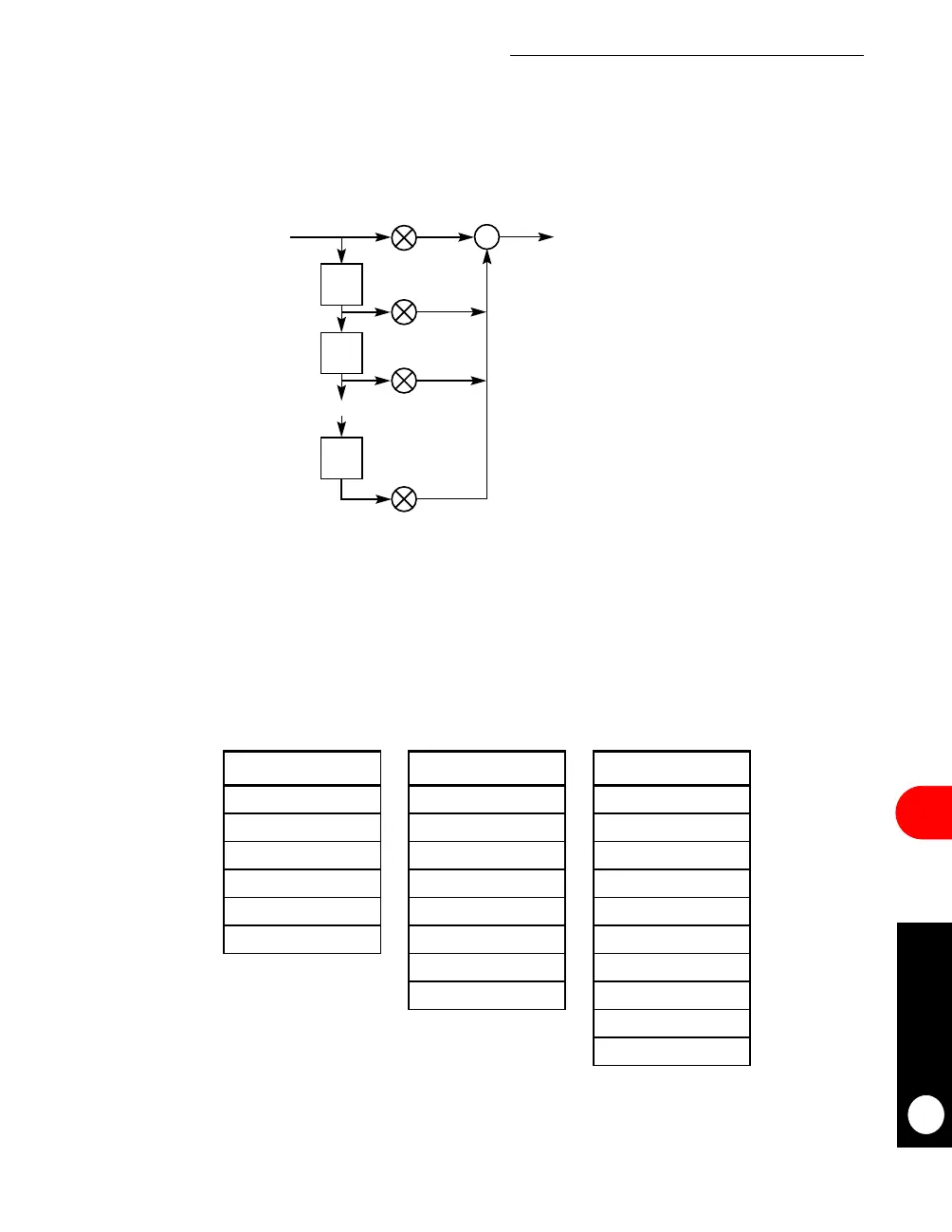
16.3.4.1 FIR1–REAL C, REAL X, AND REAL Y. The FIR1 function implements a basic
FIR filter with k real coefficients, real input samples, and real output. The input data is in a
circular buffer with size M+1 and the output data is in a circular buffer with size N+1.
16.3.4.1.1 Coefficients and Sample Data Buffers. The coefficients vector occupies k
16-bit half-words in memory and C(0) is stored in the first location. The sample input buffer
is a cyclic buffer containing M+1 bytes. Each sample is a 16-bit word and the new sample is
stored in the address that follows the previous sample. The output buffer is a cyclic buffer
that contains N+1 bytes. Each output is a 16-bit half-word and the new output is stored in
the address that follows the previous output.
Figure 16-12. FIR1 Implementation Example
COEFFICIENTS INPUT SAMPLES OUTPUT
C(0) * *
C(1) * *
C(2) x(N-k+1) *
**
* Y(N-k+1)
C(k-1) x(N-2) *
x(N-1) *
x(N) Y(N-2)
Y(N-1)
Y(N)
2K bytes M + 1 bytes N + 1 bytes
Figure 16-13. FIR1 Coefficients and Sample Data Buffers
T
T
T
X(N)
Y(N)
C(0)
C(1)
C(2)
C(K-1)
{REAL}
{REAL}
{REAL}
Yn
()
Cp
()
Xn p
–()
p0=
k1
–
∑
=
∑



 To Next Page